Heat dissipating fan

a technology of heat dissipating fans and fans, which is applied in the direction of instruments, horology, structural associations, etc., can solve the problems of troublesome mounting of the conventional heat dissipating fan having an inner-rotor-type motor in the fan housing, affecting the heat dissipation effect of electronic products, etc., to achieve enhanced heat dissipation effect and enhanced rotational stability

Active Publication Date: 2010-09-21
SUNONWEALTH ELECTRIC MACHINE IND
View PDF13 Cites 17 Cited by
  • Summary
  • Abstract
  • Description
  • Claims
  • Application Information

AI Technical Summary

Benefits of technology

[0007]The primary object of the present invention is to provide a heat dissipating fan including a fan housing receiving an inner-rotor-type motor to provide enhanced rotational stability and enhanced heat dissipating effect.
[0008]Another object of the present invention is to provide a heat dissipating fan including a fan housing that has an integrally formed motor casing receiving an inner-rotor-type motor to provide enhanced assembling convenience.
[0009]A further object of the present invention is to provide a heat dissipating fan including a circuit board and a stator spaced from the circuit board to prevent the heat dissipating effect of the circuit board from being adversely affected by the large amount of heat resulting from operation of the stator.
[0015]The heat dissipating fans according to the preferred teachings utilizes inner-rotor-type motors that rotate stably to enhance the overall heat dissipating effect of the heat dissipating fans. Furthermore, the heat dissipating fans according to the preferred teachings of the present invention utilizes a fan housing having an integral motor casing for receiving an inner-rotor-type motor to provide more convenient assembly than conventional heat dissipating fans utilizing inner-rotor-type motors. Further, since the circuit board and the stator are spaced apart from each other by the partitioning member, the heat dissipating effect of the circuit board is prevented from being adversely affected by the large amount of heat resulting from operation of the stator. Thus, damage to the associated electronic elements can be avoided.

Problems solved by technology

Unfortunately, the conventional heat dissipating fans having outer-rotor-type motors can not fulfill the heat dissipation need of these electronic products.
However, mounting of the conventional heat dissipating fan having an inner-rotor-type motor in the fan housing is troublesome.
As a result, damage to electronic elements is liable to occur, for heat dissipation of the driving device 64 is not easy.

Method used


Image

  • Heat dissipating fan
  • Heat dissipating fan
  • Heat dissipating fan

Examples


first embodiment

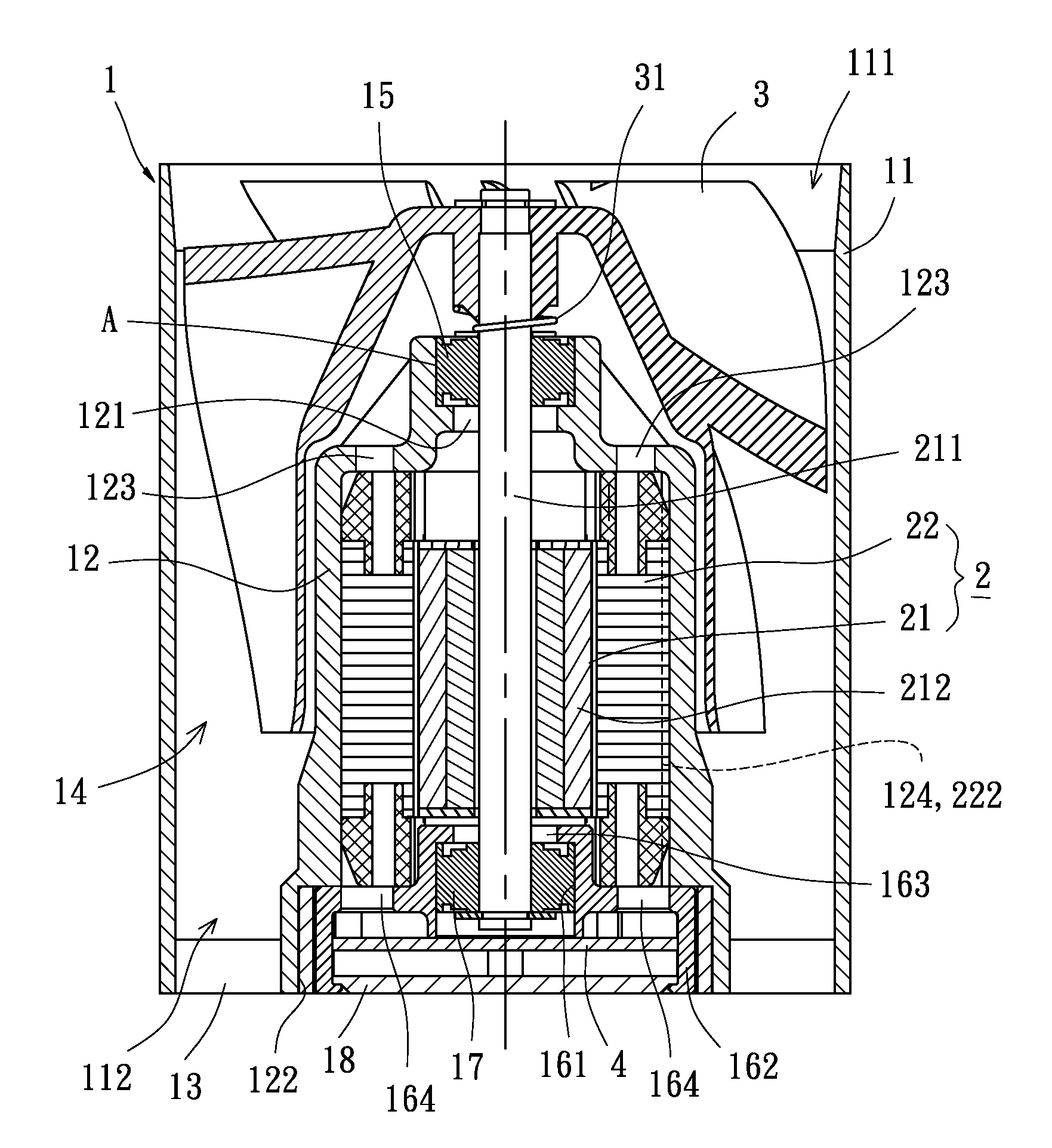
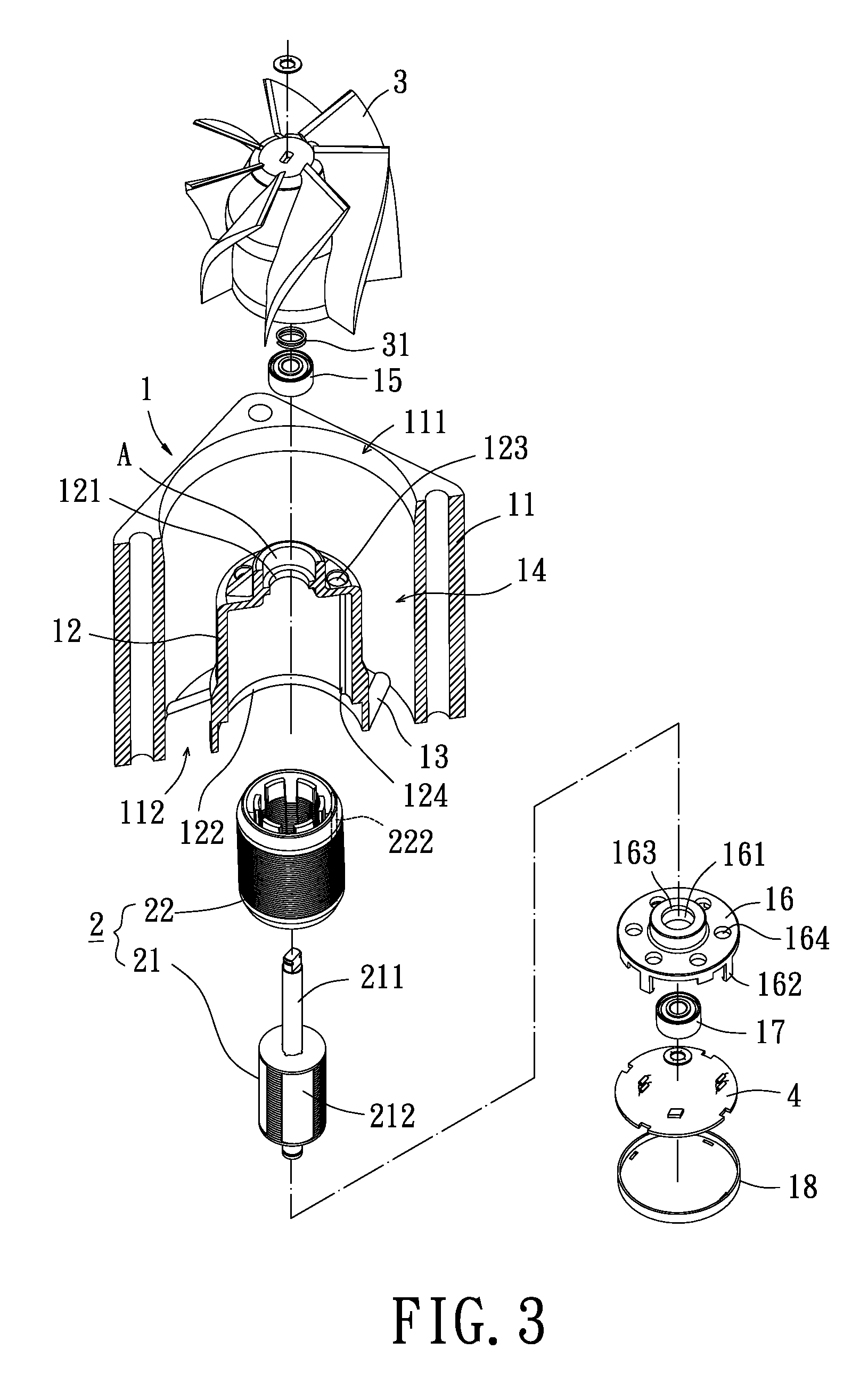
[0025]FIGS. 3 through 5 show a heat dissipating fan of a first embodiment according to the preferred teachings of the present invention. According to the preferred form shown, the heat dissipating fan includes a fan housing 1, an inner-rotor-type motor 2, an impeller 3, and a circuit board 4. The fan housing 1 is an integrally formed housing in which the motor 2 is mounted. The impeller 3 is coupled with the motor 2. The circuit board 4 is electrically connected to the motor 2 to control the motor 2 for driving the impeller 3 to rotate.

[0026]According to the preferred form shown, the fan housing 1 includes an outer frame portion 11 having an air inlet 111 and an air outlet 112 respectively in two ends thereof. A hollow motor casing 12 is formed in and integral with the outer frame portion 11. Preferably, the motor casing 12 is connected to the outer frame portion 11 by at least one connecting member 13, defining a passageway 14 between the motor casing 12 and the outer frame portion...

second embodiment

[0036]The impellers 3 are respectively mounted to the ends of the shaft 211 extending beyond the first and second openings 121 and 122 so that the impellers 3 are in alignment with the air inlet 111 and the air outlet 112 of the fan housing 1. The connecting member 13 is located between the impellers 3. A resilient element 31 is mounted between one of the impellers 3 and the first bearing 15 to allow stable rotation of the impeller 3 and to form a heat dissipating fan having an inner-rotor-type motor 2. The heating dissipating fan of the second embodiment according to the preferred teachings of the present invention utilizes the motor 2 to simultaneously rotate the impellers 3 to guide air current into the passageway 14 via the air inlet 111 of the fan housing 1. The air current is concentrated in the passageway 14 and then guided out of the air outlet 112 to dissipate heat generated by the electronic products.

[0037]As mentioned above, the heat dissipating fans according to the pref...


PUM


Abstract

A heat dissipating fan includes a fan housing having an outer frame portion. An air inlet and an air outlet are respectively defined in two ends of the outer frame portion. A hollow motor casing is formed in and integral with the outer frame portion. An inner-rotor-type motor is mounted in the motor casing and includes a rotor and a stator. The rotor is rotatably received in the stator and includes a shaft and a magnetic element. The shaft extends beyond the motor casing. The magnetic element is coupled with the shaft and faces the stator. At least one impeller is coupled to the shaft and located outside the motor casing. A circuit board is electrically connected to the stator.

Description

BACKGROUND OF THE INVENTION[0001]1. Field of the Invention[0002]The present invention relates to a heat dissipating fan and, more particularly, to a heat dissipating fan including a motor having an inner rotor.[0003]2. Description of Related Art[0004]FIG. 1 shows a conventional heat dissipating fan including an outer-rotor-type motor. Specifically, the heat dissipating fan includes a frame 51, a stator 52, a circuit board 53, and a rotor 54. An axle tube 511 is formed in the frame 51 and receives at least one bearing 512. The stator 52 and the circuit board 53 are mounted around the axle tube 511, with the stator 52 electrically connected to the circuit board 53. The rotor 54 includes a shaft 541 and an impeller 542 mounted to an end of the shaft 541. The shaft 541 is extended into the axle tube 511 and rotatably held by the bearings 512. The impeller 542 includes a permanent magnet 543 facing the stator 52. The circuit board 53 controls the stator 52 and the permanent magnet 543 to...

Claims


Application Information

Patent Timeline
Patent Type & Authority Patents(United States)
IPC IPC(8): H02K7/00H02K11/00
CPCH02K1/185H02K5/1732H02K7/14H02K11/0073H02K11/33
Inventor HORNG, ALEXYIN, TSO-KUO
Owner SUNONWEALTH ELECTRIC MACHINE IND
Why Eureka
Try Eureka