Fluid dynamic bearing system to rotatably support a spindle motor

Inactive Publication Date: 2006-04-13
MINEBEA CO LTD
View PDF3 Cites 19 Cited by
  • Summary
  • Abstract
  • Description
  • Claims
  • Application Information

AI Technical Summary

Benefits of technology

[0007] The object of the invention is to improve a fluid dynamic bearing system for spindle motors in such a way that the use of a central fastening screw in co

Problems solved by technology

In spindle motors having stationary shafts, as employed in hard disk drives, it is not possible to use a central fastening screw (clamping screw),

Method used


Image

  • Fluid dynamic bearing system to rotatably support a spindle motor
  • Fluid dynamic bearing system to rotatably support a spindle motor
  • Fluid dynamic bearing system to rotatably support a spindle motor

Examples


Embodiment Construction

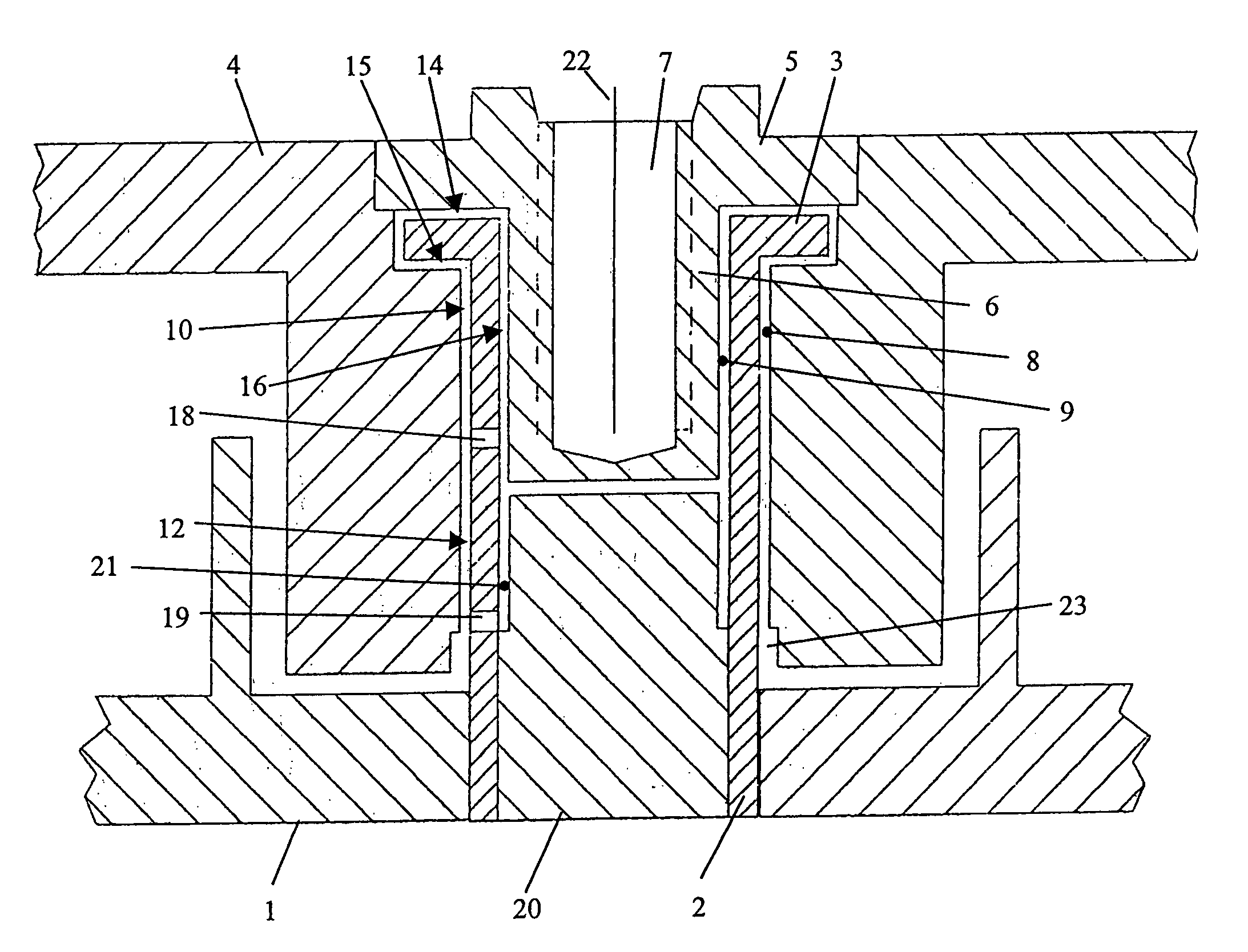
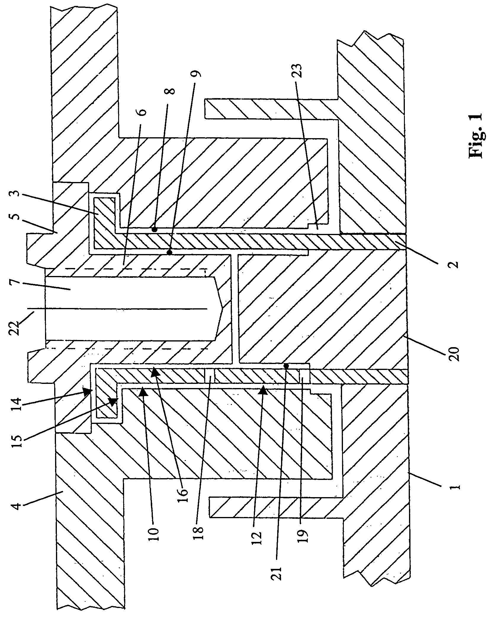
[0022]FIG. 1 shows a schematic sectional view of a spindle motor to drive a hard disk drive having a fluid dynamic bearing system according to the invention. The electromagnetic components needed to operate the spindle motor, such as stator windings, permanent magnets, etc. are not illustrated in the drawing.

[0023] The spindle motor comprises a stationary baseplate 1. A hollow shaft 2 is arranged in an opening in the baseplate 1 and firmly fixed to the baseplate. At its free end, the hollow shaft 2 comprises an annular flange which forms a thrust plate 3 as part of an axial bearing as described below. The shaft 2 and thrust plate 3 may be formed integrally and are enclosed by a bearing sleeve 4 that has an axial cylindrical bore to receive the shaft 2. The thrust plate 3 is accommodated in a larger diameter annular recess in the bearing sleeve. The inside diameter of the bore or recess in the bearing sleeve 4 is slightly larger than the outside diameter of the shaft or the outside ...


PUM


Abstract

The invention relates to a fluid dynamic bearing system for the particular purpose of rotatably supporting a spindle motor used to drive the disk(s) of a hard disk drive having a stationary shaft, a thrust plate connected to the shaft, a bearing sleeve rotatable about the rotational axis of the shaft and a cover sealing the bearing sleeve, wherein the surfaces of the shaft, the thrust plate, the bearing sleeve and the cover, that face each other and are separated from each other by a fluid-filled bearing gap, form at least one radial bearing region and at least one axial bearing region. According to the invention, the shaft is designed as a hollow shaft, and the cover has a cylindrical section concentric to the rotational axis that is rotatably accommodated in the hollow shaft in such a way that between the inside diameter of the hollow shaft and the outside diameter of the cylindrical section of the cover, an inner bearing gap filled with bearing fluid is formed, the inner bearing gap being connected to the outer bearing gap.

Description

BACKGROUND OF THE INVENTION [0001] The invention relates to a fluid dynamic bearing system for the particular purpose of rotatably supporting a spindle motor used, for example, to drive the disk(s) of a hard disk drive according to the preamble of claim 1. PRIOR ART [0002] Spindle motors essentially consist of a stator, a rotor and at least one bearing system arranged between these two parts. The electrically driven rotor is rotatably supported with respect to the stator by means of the bearing system. Included among the kinds of bearings used in bearing systems are roller bearings and fluid or fluid dynamic bearing systems. [0003] A well-known embodiment of a fluid dynamic bearing system, revealed, for example, in DE 201 19 716 U1, comprises a stationary shaft and a bearing sleeve that has an axial bore to receive the shaft. The sleeve rotates freely about the stationary shaft and forms a radial bearing together with the shaft. The mutually interacting bearing surfaces of the shaft...

Claims


Application Information

Patent Timeline
IPC IPC(8): F16C32/06
CPCF16C17/026F16C17/10F16C33/107G11B19/2018F16C2370/12
Inventor BRAUN, DIETER
Owner MINEBEA CO LTD
Why Eureka
Try Eureka