

Scanning welding torch
A welding torch and welding wire technology, applied in the field of scanning welding torch, can solve the problems of increasing the size of the welding torch, inconvenient adjustment, high manufacturing precision, etc., and achieve the improvement of rotation accuracy and stability, flexibility and practicability, size and weight Reduced effect
- Summary
- Abstract
- Description
- Claims
- Application Information
AI Technical Summary
Problems solved by technology
Method used
Image

Examples
Embodiment 1
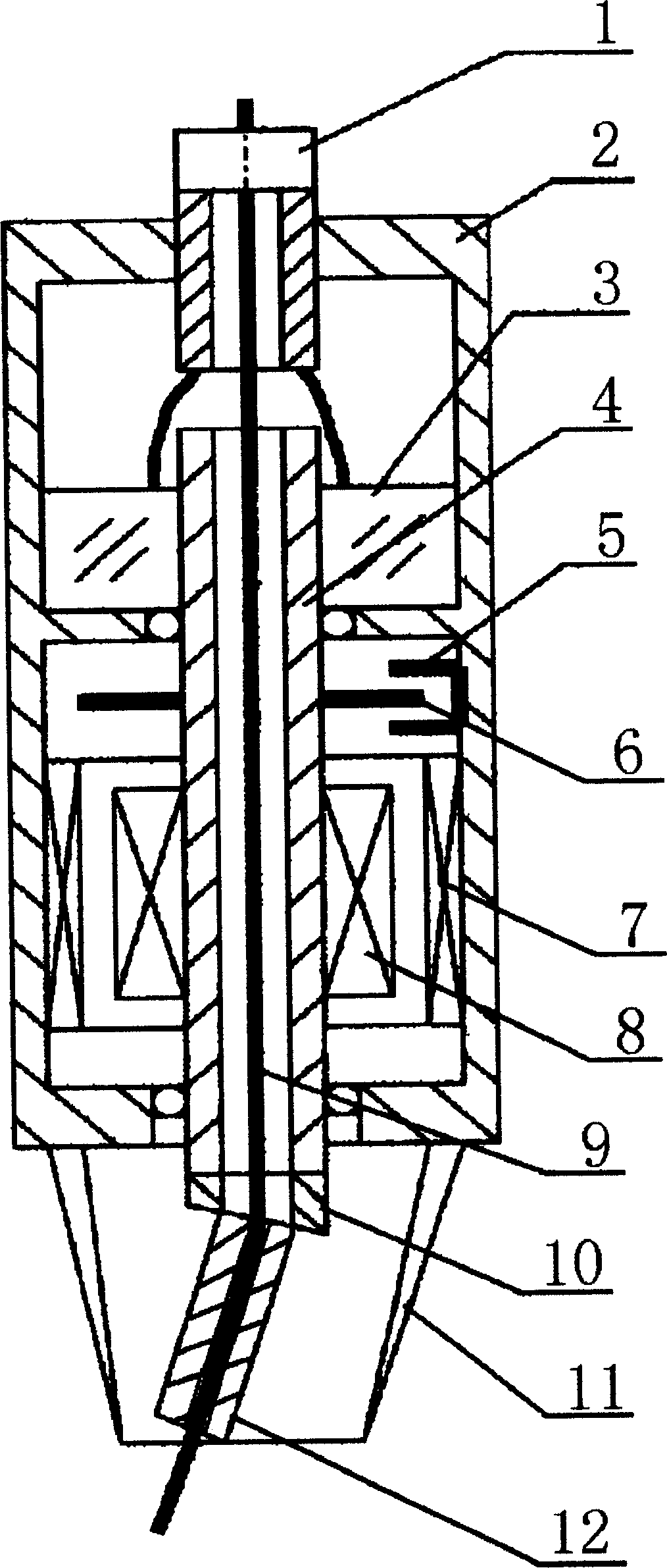
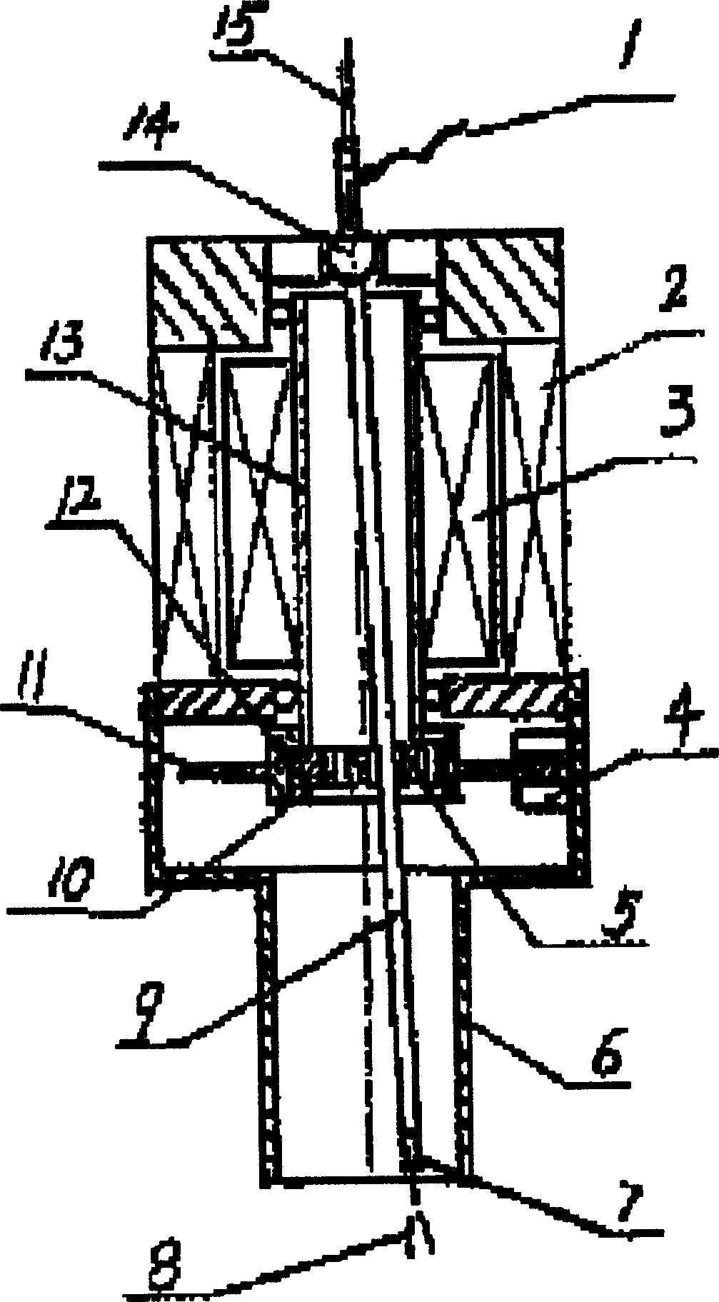
[0011] Embodiment 1, by figure 1 It can be seen that the present invention includes a motor, a carbon brush 3 and a standard gas shielded welding cable, and the motor composed of a stator 7 and a rotor 8 is set in the housing 2, and the cable connected to the gas shielded welding cable, the welding wire 9 and the shielding gas pipeline are integrated The chemical joint 1 is sealed and fixedly installed on the upper part of the shell 2, the protective gas pipeline communicates with the inner cavity of the sealed shell 2 through the integrated joint 1, and the conductive rod 4 is relatively fixed in the shell 2 through the bearing on it. The upper end of the conductive rod 4 communicates with the inner cavity of the housing 2, and the two or three carbon brushes 3 installed in dynamic cooperation with the conductive rod 4 are electrically connected with the integrated joint 1. The conductive rod 4 passes through the motor rotor 8 and connects with the The motor rotor 8 is fixed...
Embodiment 2
[0012] In Embodiment 2, an optical code disk 6 matched with an optical couple 5 is installed in the middle of the conductive rod 4, so that the digital control of the rotary scanning welding torch can be realized. All the other are with embodiment 1.
Embodiment 3
[0013] Embodiment 3, the lower end surface of the rotary joint 10 fixedly connected to the lower end of the conductive rod 4 is an inclined plane, so that the conductive tip 12 fixed on the inclined surface of the lower end of the rotary joint 10 and the conductive rod 4 are inclined at an angle. The rotary scanning range can be adjusted in steps by replacing the rotary connectors with different inclined end faces, and the rotary connectors can be selected according to different welding processes. All the other are with embodiment 1 and 2.
PUM
 Abstract
Description
Claims
Application Information