Airbag device

a technology for airbags and inflators, which is applied in the direction of vehicle components, pedestrian/occupant safety arrangements, vehicular safety arrangments, etc., can solve the problems of long time and muscle power required of operators to mount the inflator, and achieve the effect of convenient insertion, convenient insertion and convenient insertion

Inactive Publication Date: 2006-10-24
TAKATA CORPORATION
View PDF34 Cites 25 Cited by
  • Summary
  • Abstract
  • Description
  • Claims
  • Application Information

AI Technical Summary

Benefits of technology

[0035]In the airbag device of the present invention, since the shape-maintaining component is connected to the front portion of the airbag, the front portion of the airbag is located away from the inflator insertion port because the front portion of the airbag is pulled by the shape-maintaining component. Consequently, a space is provided between the airbag front portion and the inflator insertion port, so that the front-end side of the inflator is easily inserted into the folded body.
[0036]In the present invention, the connecting portion of the shape-maintaining component and the airbag front portion is preferably located in the direction of extension of the inflator insertion direction into the above-described inflator insertion port. With this configuration, the above-described space extends from the inflator insertion port toward the inflator insertion direction, so that the inflator is easily inserted.
[0037]In this case, the above-described connecting portion is preferably located at the front side of the above-described folded airbag, and a portion of the above-described airbag in the vicinity of the connecting portion extends from the front side toward the periphery of the above-described inflator insertion port. With this configuration, a size of the above-described space in the vicinity of the inflator insertion port is increased, so that the inflator is further easily inserted.

Problems solved by technology

Therefore, the operator is required to have a significant muscle power and, in addition, it takes long time to mount the inflator.

Method used


Image

  • Airbag device
  • Airbag device
  • Airbag device

Examples


Embodiment Construction

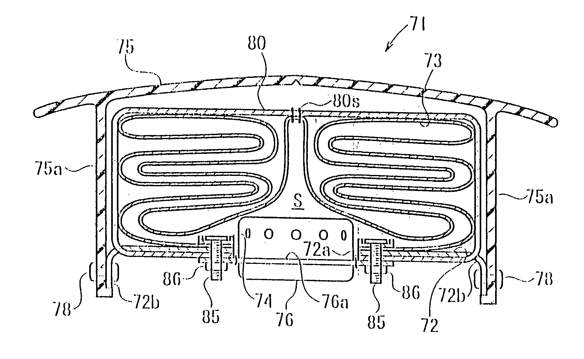
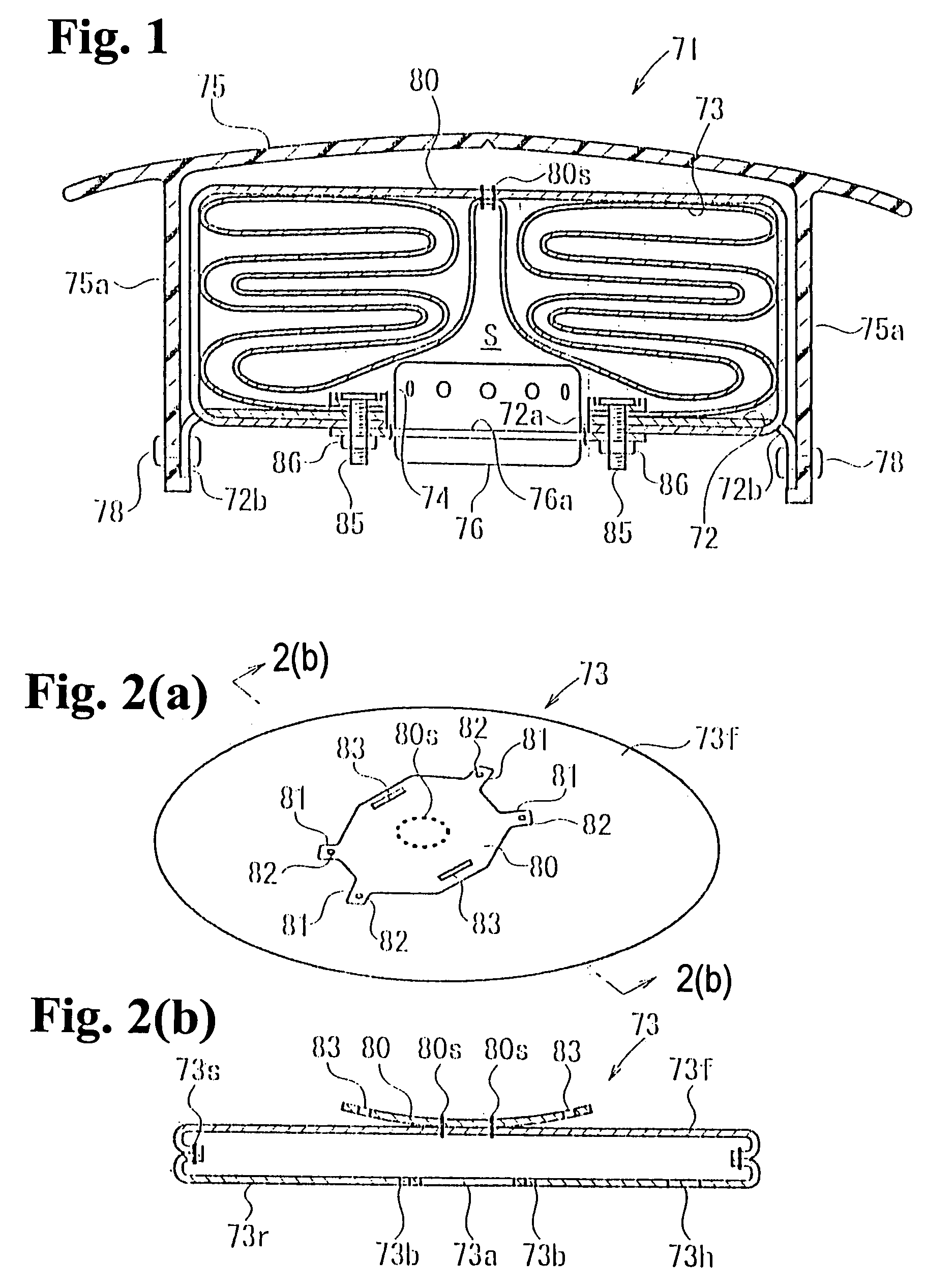
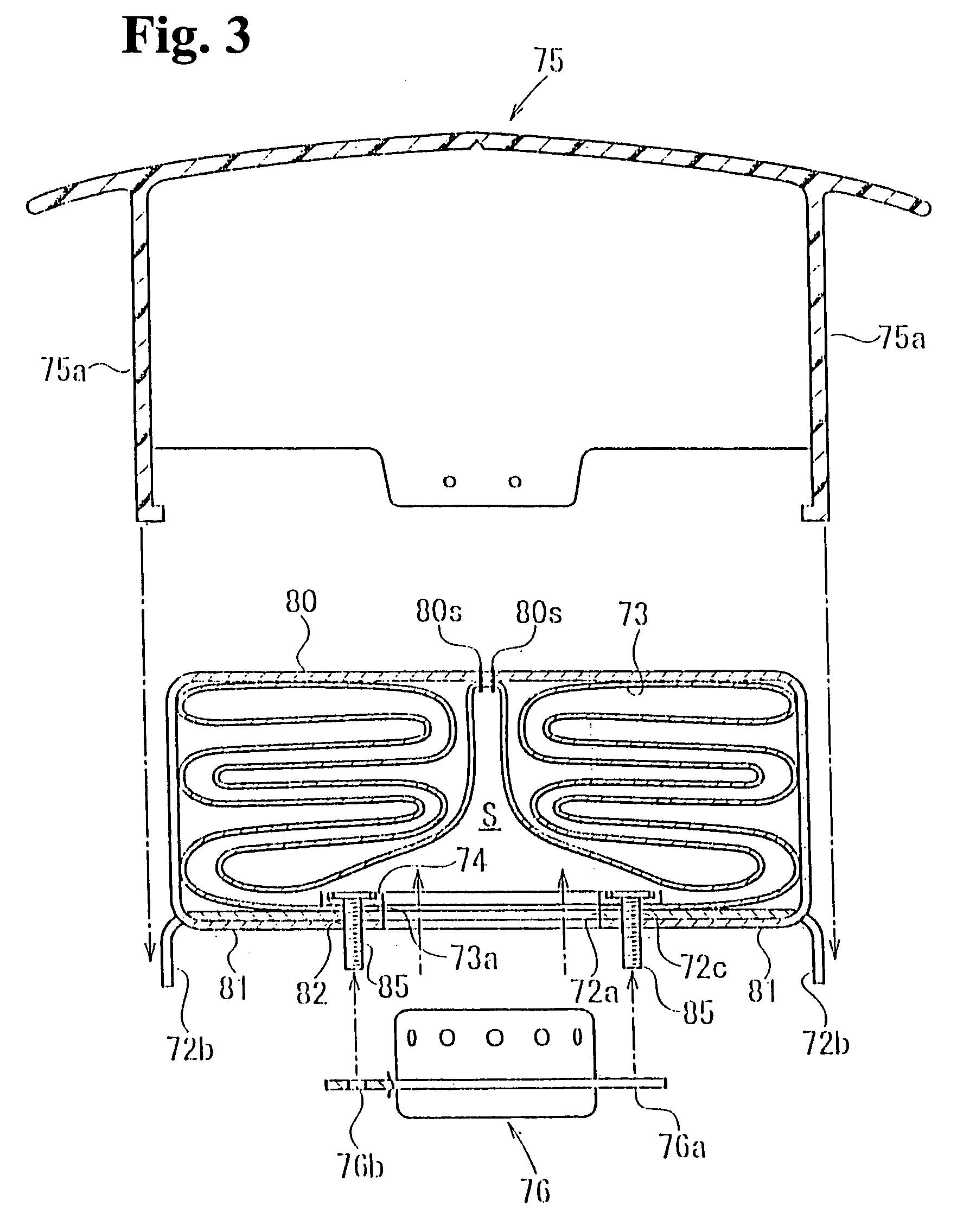
[0053]Embodiments of the present invention will be described below with reference to the accompanying drawings. FIG. 1 is a vertical sectional view of a driver airbag device according to an embodiment. FIG. 2(a) is a perspective view of an airbag in a flat spread state before folding, and FIG. 2(b) is a sectional view taken along line 2(b)—2(b) in FIG. 2(a). FIG. 3 is an exploded view of the airbag device. FIG. 4 is a perspective view showing a folded body viewed from above. FIGS. 5 and 6 are perspective views showing the folded body (before a shape-maintaining component covers) viewed from below and above.

[0054]The airbag device 71 includes a retainer (base plate) 72, an airbag 73 mounted on the retainer 72 with an airbag-mounting ring 74, an inflator 76 to inflate the airbag 73, a shape-maintaining component 80 to maintain a folded shape of the airbag 73, a module cover 75 covering a folded body, and the like.

[0055]The retainer 72 is provided with an inflator insertion port 72a at...


PUM


Abstract

An airbag device is provided with a retainer, an airbag mounted on the retainer, an airbag-mounting ring to mount the airbag to the retainer, an inflator to inflate the airbag, a shape-maintaining component to maintain a folded shape of the airbag, and a module cover covering the folded airbag. The shape-maintaining component is fixed to bolts. A central portion of the shape-maintaining component is attached to a central portion of a front panel of the airbag with a seam thread. When the inflator is mounted on the retainer, since a space is provided in the retainer, a front-end side of the inflator is smoothly inserted.

Description

BACKGROUND OF THE INVENTION AND RELATED ART STATEMENT[0001]The present invention relates to an airbag device to protect a vehicle occupant in the event of a collision and the like, and more specifically, relates to an airbag device to be assembled while a folded shape of an airbag is maintained by a shape-maintaining component.[0002]In general, an airbag device serving as a protector for an occupant in a vehicle and the like is configured to include an folded airbag, an inflator to supply gas to the airbag, bag holding components, e.g., a base plate and a case, on which the airbag and the inflator are mounted and fixed, and a cover which is disposed to cover a top surface of the folded airbag and which is torn by an inner pressure of the airbag when the airbag device is actuated.[0003]In such an airbag device, the folded shape of the airbag may be maintained with a shape-maintaining component for the purposes of improving workability in mounting of the above-described cover and of p...

Claims


Application Information

Patent Timeline
Patent Type & Authority Patents(United States)
IPC IPC(8): B60R21/16B60R21/20B60R21/203B60R21/215B60R21/201B60R21/217B60R21/237
CPCB60R21/201B60R21/217B60R21/237
Inventor AMAMORI, ICHIRO
Owner TAKATA CORPORATION
Why Eureka
Try Eureka