Projection system with corrective image transformation

a projection system and image technology, applied in the field of projectors, can solve the problems of affecting the corrective effect of users,

Active Publication Date: 2006-10-24
SHARP KK
View PDF38 Cites 64 Cited by
  • Summary
  • Abstract
  • Description
  • Claims
  • Application Information

AI Technical Summary

Problems solved by technology

However, if the alignment and orientation is modified, then the resulting image on the projection surface may be distorted.
However, in many situations, it may not be feasible to sufficiently physically adjust the position of the projector.
This is a burdensome task for a user to correctly perform.
The determination and inputting of positional information is difficult and burdensome for the user.
Unfortunately, the tilt sensors tend to be expensive and the system requires complex re-calibration when the projector lens moves, e.g., when the projector is zoomed and / or focused.
This inherent complexity increases the expense of the resulting projector.

Method used


Image

  • Projection system with corrective image transformation
  • Projection system with corrective image transformation
  • Projection system with corrective image transformation

Examples


Embodiment Construction

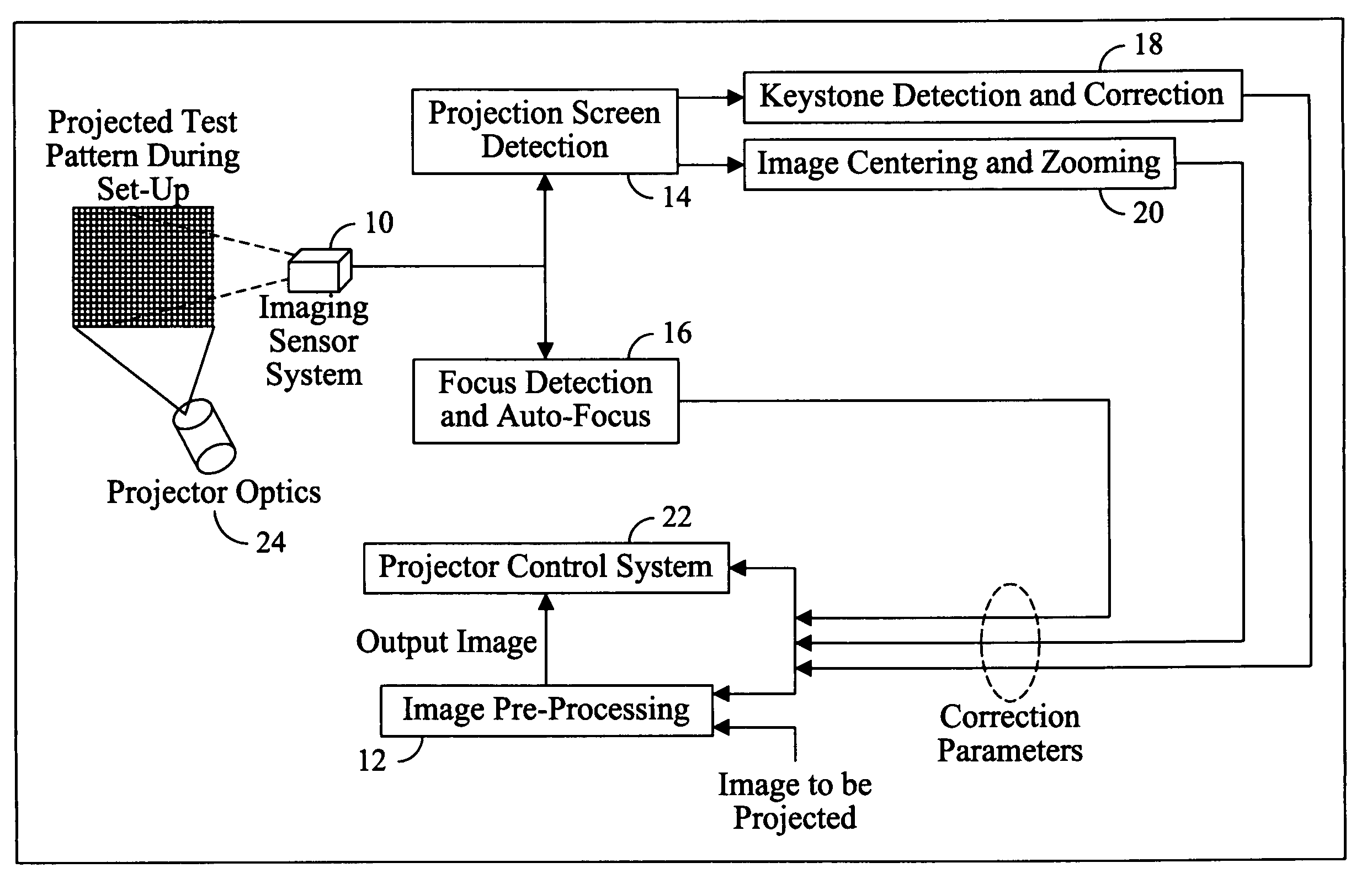
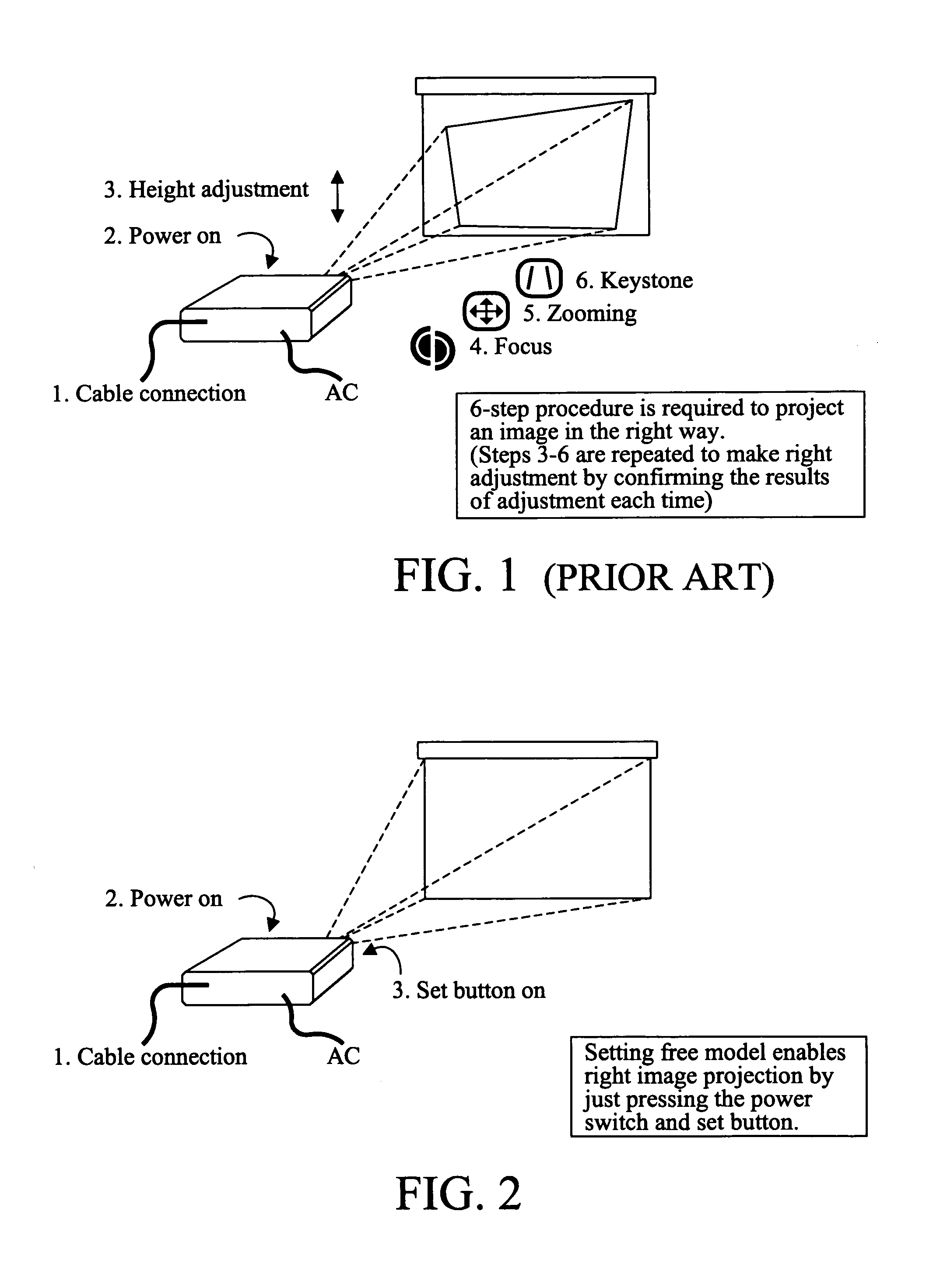
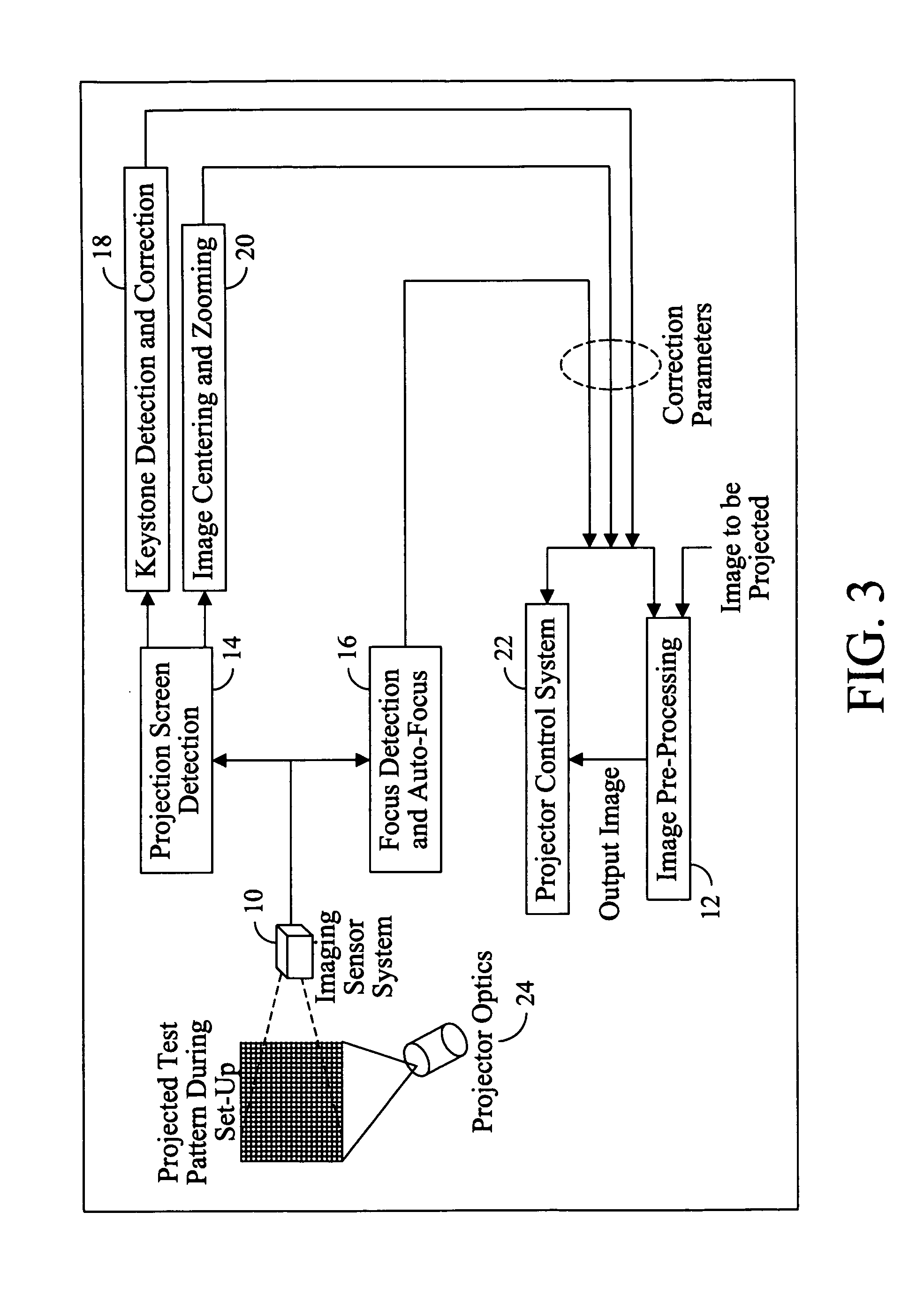
[0037]Referring to FIG. 1, a typical projection system includes an enclosure housing the electronics and imaging devices. To set up a projector to display an image properly many steps are performed which typically include, (1) connecting a cable to a laptop or other image source, (2) switching a power switch (on / off), (3) adjusting the vertical angle of projection, (4) focusing the image on the display, (5) adjusting the zoom of the image, and (6) manually adjusting the keystone. As it may be observed, this includes many steps which typically need to be performed in a suitable order. Referring to FIG. 2, a modified projection system includes an enclosure housing the electronics and imaging devices. To set up the modified projector to display an image properly fewer steps are performed which typically include, (1) connecting a cable to a laptop or other image source, (2) switching a power switch (on / off), and (3) selecting the auto-set up function. As it may be observed this requires...


PUM


Abstract

An image projection system that corrects an image to be projected onto a projection surface by sensing at least a portion of that surface, and based upon the sensed portion, determining and applying a corrective transformation to the image, after which the corrected image is projected onto the projection surface.

Description

BACKGROUND OF THE INVENTION[0001]This invention relates generally to image projectors, and more particularly, to modifying projected images.[0002]Portable digital image projectors are common. Such digital image projectors, while connected to a personal computer or other image / video source, sit on a surface and are directed at a projection surface to show a “slide” presentation or a video presentation. Many of these projectors use transmissive or reflective liquid crystal displays, and typically only have a single main lens. Other such projectors use different imaging devices, such as digital micro-mirrors, and may include more than one lens. The projectors can display images one at the time or as a sequence of images, as in the case of video.[0003]These digital projectors are typically designed so that undistorted rectangular images are projected on the projection surface when the projector is placed horizontally on a level support surface with the projector's optical axis lined up ...

Claims


Application Information

Patent Timeline
Patent Type & Authority Patents(United States)
IPC IPC(8): G03B21/00G03B21/14H04N5/74H04N9/31H04N17/00
CPCH04N5/74H04N9/3185H04N9/3194H04N9/3197
Inventor LI, BAOXINKOJIMA, SHIGERUFURUHASHI, TOSHINORIARAKAWA, KAZUYAYONEZAWA, RYOHICHI
Owner SHARP KK
Why Eureka
Try Eureka