Application specific, dual mode projection system and method

a projection system and dual-mode technology, applied in the field of application specific projection systems, can solve the problems of relatively complicated and expensive circuits of the lcos driver, and achieve the effect of saving both cost and complexity, and facilitating the configuration of the on-chip pattern generator

Active Publication Date: 2017-09-12
OMNIVISION TECH INC
View PDF20 Cites 164 Cited by
  • Summary
  • Abstract
  • Description
  • Claims
  • Application Information

AI Technical Summary

Benefits of technology

[0008]The present invention overcomes the problems associated with the prior art by providing an integrated circuit display device with an on-chip pattern generator. The invention facilitates configuring the on-chip pattern generator to provide application specific display patterns, thereby enabling the construction of application specific projectors that do not require a separate driver circuit for processing video data from an external source. The elimination of the driver circuit results in a significant savings in both cost and complexity.

Problems solved by technology

Of course, LCOS drivers are relatively complicated and expensive circuits.

Method used


Image

  • Application specific, dual mode projection system and method
  • Application specific, dual mode projection system and method
  • Application specific, dual mode projection system and method

Examples


Embodiment Construction

[0032]The present invention overcomes the problems associated with the prior art, by providing a projector with display panel including an integrated circuit backplane with an application specific display pattern generator thereon. In the following description, numerous specific details are set forth (e.g. structured light application patterns) in order to provide a thorough understanding of the invention. Those skilled in the art will recognize, however, that the invention may be practiced apart from these specific details. In other instances, details of well-known display panel operation and manufacturing practices (e.g., application of liquid crystal, digital data transfer, circuit timing, etc.) and components have been omitted, so as not to unnecessarily obscure the present invention.

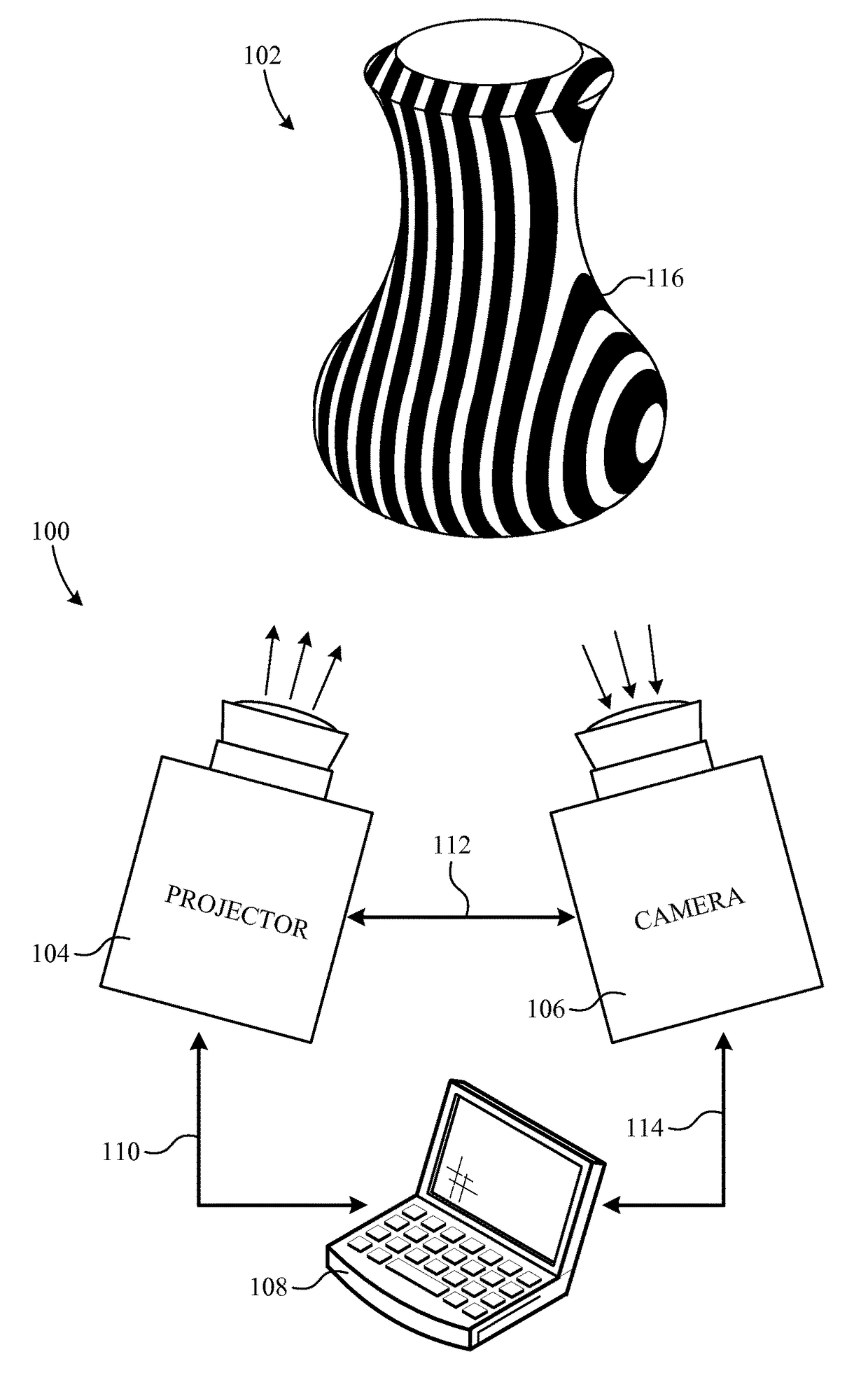
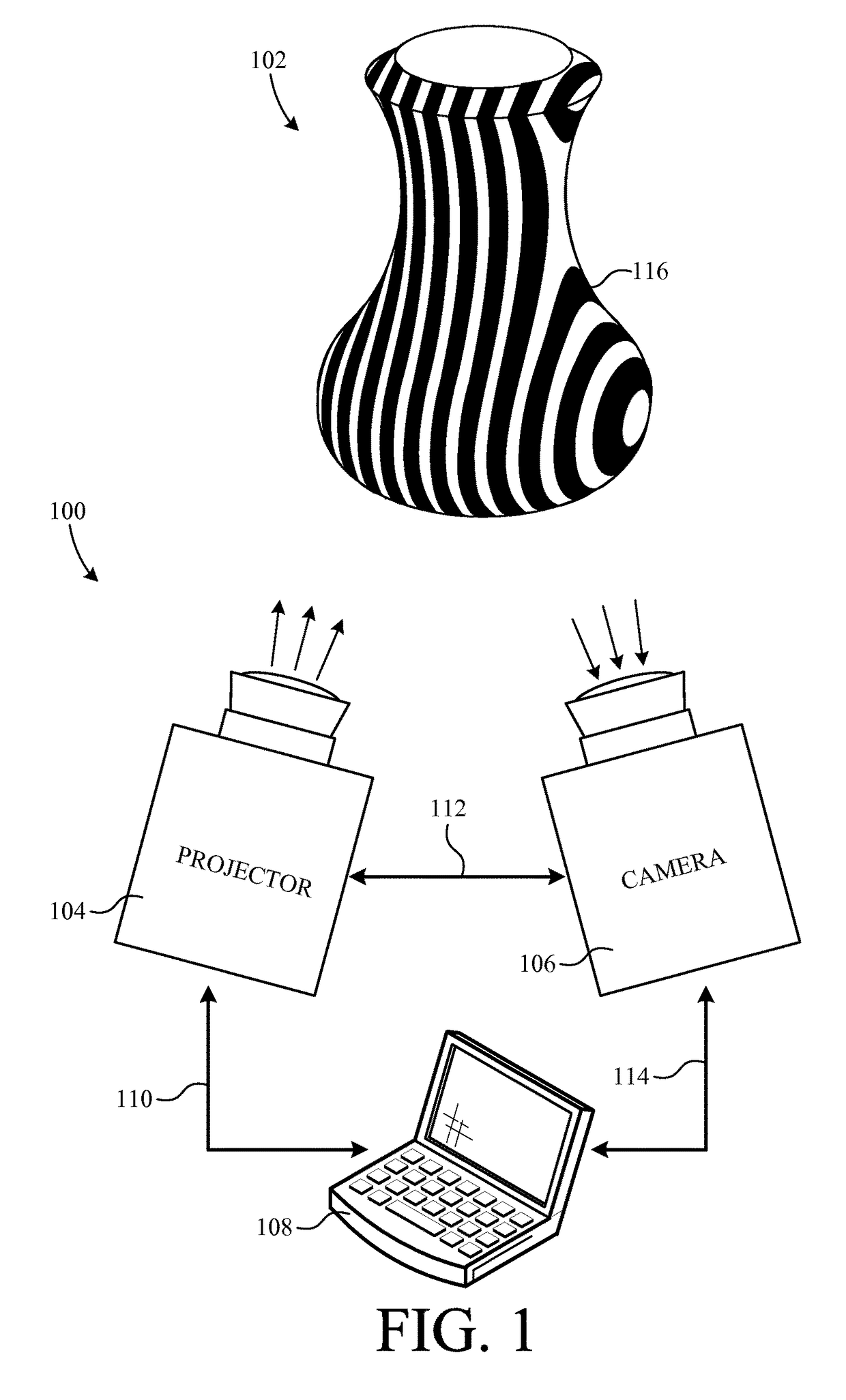
[0033]FIG. 1 shows a structured light system 100 scanning the topography of a three-dimensional object which, in this example, is a pot 102. Structured light system 100 includes a projector 104, a c...


PUM

PropertyMeasurementUnit
non-volatile memoryaaaaaaaaaa
time durationaaaaaaaaaa
timeaaaaaaaaaa

Abstract

A projector panel includes pixel display, a display controller, and a pattern generator. The pattern generator is operative to output pixel data indicative of at least one application specific predetermined pattern. In a particular embodiment, the projector panel is a liquid-crystal-on-silicon panel. In another particular embodiment, the projector panel is adapted for selective use in either structured light projection systems or conventional video projection systems.

Description

BACKGROUND OF THE INVENTION[0001]Field of the Invention[0002]This invention relates generally to application specific projection systems and more particularly to three-dimensional object scanning systems. Even more particularly, the invention relates to structured light scanning systems.[0003]Description of the Background Art[0004]Structured light scanning systems are currently being used to measure the three-dimensional topography of objects. Such systems typically include a computer connected to both a projector (e.g., a liquid crystal on silicon (LCOS) projector) and a camera. During operation, the projector projects a plurality of narrow light bands on a three-dimensional surface or object. From the perspective of the projector, the narrow light bands appear as evenly distributed vertical and / or horizontal stripes. From the perspective of the camera, however, the narrow light bands appear as distorted stripes. The camera captures images of these distorted stripes and sends the i...

Claims


Application Information

Patent Timeline
Patent Type & Authority Patents(United States)
IPC IPC(8): H04N5/74G01B11/25G09G3/00
CPCG01B11/2513G09G3/002G09G2310/0205Y10T29/49002
Inventor NG, SUNNY YAT-SANLU, MANUEL
Owner OMNIVISION TECH INC
Why Eureka
Try Eureka