Device for driving a light receiving element to track a light source

a technology of light receiving element and light source, which is applied in the direction of photometry, solar heat collector moving/orientation, solar radiation concentration, etc., can solve the problems of mechanical tracking system adding significant cost to the final device, photovoltaics are expensive to produce, and historically been attractive sources of power, etc., to save the cost and complexity of providing, and the effect of strong tension

Active Publication Date: 2015-01-27
CHITENDAI LTD
View PDF4 Cites 0 Cited by
  • Summary
  • Abstract
  • Description
  • Claims
  • Application Information

AI Technical Summary

Benefits of technology

[0033]The invention provides a structure that has reduced component count and assembly complexity and hence reduced cost. Reliability issues, such as the concern over dirt particles affecting bearings or sliding contacts, are resolved or reduced. Compatibility of the invention with low cost manufacturing techniques is possible, as are techniques that allow the device to be conveniently manufactured in array format.
[0035]In one embodiment of the present invention, it is possible to use the resilient flexible beams as electrical conductors to conduct away the electrical energy collected by a photovoltaic cell, thus saving the cost and complexity of providing separate electrical connections.
[0036]In another embodiment of the present invention, an additional passive component is added to the structure. This component can comprise wires that connect the two support members that limit the gap between the support members as they are laterally displaced relative to one another. For example, wires that are strong in tension could be connected between the upper and lower support members and attached so that they are vertical in the “default” state. When a relative translation is applied to one of the support members, these wires constrain the support members to move on an arc relative to each other. This is an advantage for the described design as it stops the resilient flexible beams from extending beyond their elastic limit when a large translation is applied. It also enables a larger angle of rotation (for the element) to be achieved.

Problems solved by technology

However, photovoltaics are expensive to produce and therefore as an investment, it can take more than 10 years for a photovoltaic installation to repay its capital costs, and hence such systems have not historically been an attractive source of power.
However, mechanical tracking systems have typically added significant cost to the final devices.
Also, there are concerns about maintenance and the long term reliability of jointed mechanical systems in dusty environments.
Furthermore, due to the large angle range over which the sun moves, the motion of such systems typically means that they occupy a large volume.

Method used


Image

  • Device for driving a light receiving element to track a light source
  • Device for driving a light receiving element to track a light source
  • Device for driving a light receiving element to track a light source

Examples


Embodiment Construction

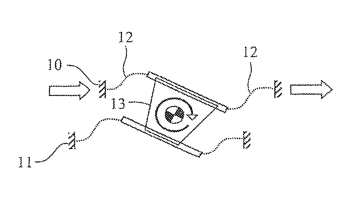
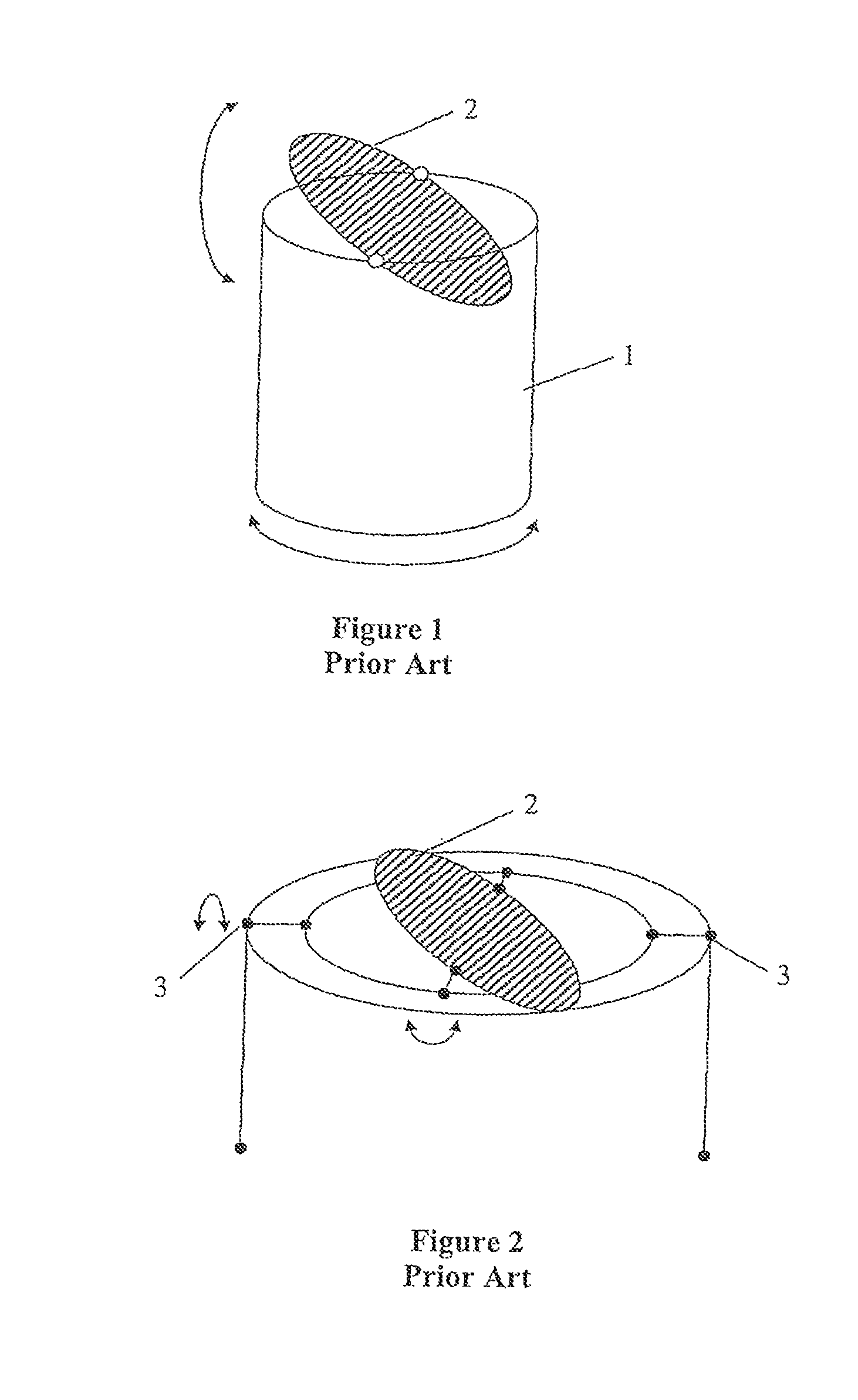
[0048]Referring to FIGS. 1 and 2 there is shown, as discussed above, examples of prior art light tracking arrangements that are used to support solar light collecting devices. In the arrangement of FIG. 1 a rotatable post 1 supports a tilting plate 2 which supports, in use, a light collecting element, so that tracking of the sun during its movement during the day can be performed to optimise light collection. In alternative arrangements following the same scheme, 1 rotatable post is used to support more than 1 tilting plate.

[0049]FIG. 2 shows an alternative arrangement in which a similar tilting plate is provided but supported on a further pivotal support component 3. In alternative arrangements following the same scheme, (e.g. U.S. Pat. No. 4,968,355, Johnson), many plates are connected to a single pivotal support

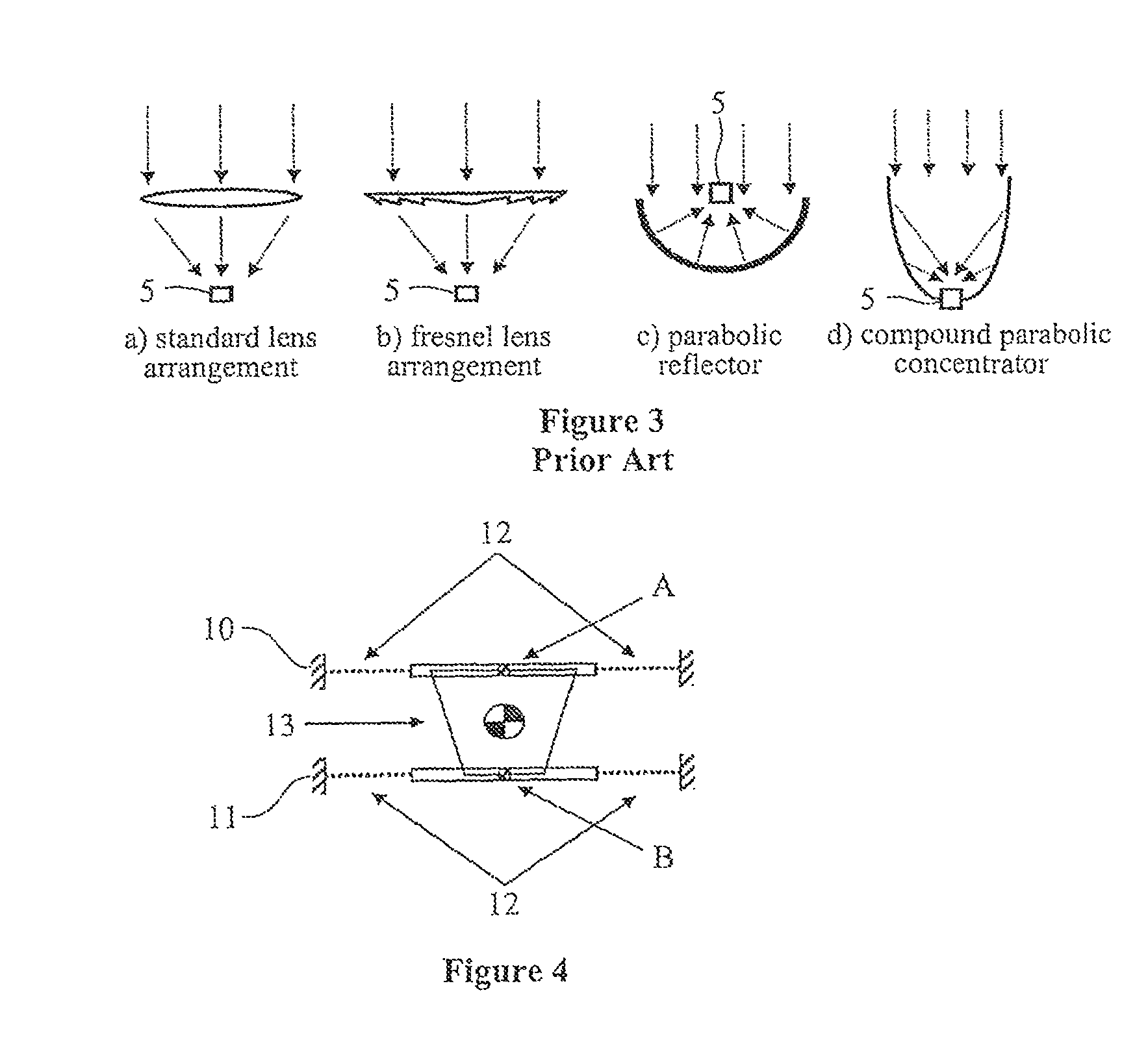
[0050]FIG. 3 shows optical elements that have been used in prior art devices and which can be employed in the present invention. In each of these a photovoltaic element 5 ...


PUM


Abstract

A light tracking device comprising first and second support members and at least one light receiving element supported on each support member by one or more resilient flexible beams which deform upon relative translational displacement of the first and second support members. The first and second support members are arranged such that relative translational displacement of the members generates rotational displacement of the element. One or more resilient flexible beams may comprise spiral arms extending from the first to the second support members.

Description

CROSS-REFERENCE TO RELATED APPLICATION[0001]This application is a continuation of application Ser. No. 12 / 742,628, filed Aug. 20, 2010, which is the National Stage of International Application No. PCT / GB2008 / 004057, filed Dec. 10, 2008.BACKGROUND[0002]The present invention relates to a light tracking device for driving one or more light receiving elements to track a light source. Particularly the invention has application in the field of solar concentrators, where the tracking device can be used to drive one or more solar-light-to-energy converting devices to track the path of the sun.[0003]Solar power is an extremely abundant source energy. Photovoltaics are used to convert the sunlight into electrical energy. Solar photovoltaic systems do not produce CO2 emissions in use and hence are a potentially interesting source of power in the future.[0004]However, photovoltaics are expensive to produce and therefore as an investment, it can take more than 10 years for a photovoltaic install...

Claims


Application Information

Patent Timeline
Patent Type & Authority Patents(United States)
IPC IPC(8): G01C21/02H01J3/14F24J2/54F24S23/00F24S23/30F24S23/70G01S3/785G01S3/786
CPCG01S3/785F24J2/08F24J2/10F24J2/5417G01S3/7861Y02E10/47Y02E10/52F24S23/30F24S23/70F24S30/45
Inventor TOMLINSON, ANDYSZCZEPANIK, JOHN-PAUL
Owner CHITENDAI LTD
Why Eureka
Try Eureka