Numeric control bore for boring an eyeglass lens and corresponding method

a technology of eyeglass lens and control bore, which is applied in the direction of large fixed members, milling equipment, measurement/indication equipment, etc., to achieve the effect of reducing the number of necessary apparatus

Inactive Publication Date: 2008-02-26
INDO INT
View PDF11 Cites 0 Cited by
  • Summary
  • Abstract
  • Description
  • Claims
  • Application Information

AI Technical Summary

Benefits of technology

[0013]Indeed, the bore according to the invention, requires one degree less of freedom than the known bores in the state of the art, with equal performances. That leads to save both in complexity and cost, as it is required one actuator less. The rotation means of the lens together with the attachment means allow moving the lens according to the polar coordinates, so that it is possible to position any point of the surface of the lens in a predetermined site. On the other hand, the support column can be rotated in a desired angle, so that the cutting tool contacts the surface of the lens with said desired angle. Usually it is interesting that the holes are made perpendicular to the lens surface, and this can be carried out with the bore according to the invention in a simple and efficient way.
[0019]Preferably, the bore according to the invention has feeler means of the lens surface working in the normal direction to said lens surface. In fact, in this way the bore can know at any moment the position of the lens surface given that, as it has been previously said, the actual lens surfaces are all slightly different between them, due, among other reasons, to the optical characteristics that they incorporate. By knowing the exact position of the lens surface, the bore can both position the head and make the hole (or in general the machining operation that corresponds) with more accuracy.
[0026]Actually, the bore according to the invention has furthermore the advantage of being extremely versatile, so that it allows carrying out a plurality of operations with it. This fact allows reducing the number of necessary apparatus in order to carry out a series of operations necessary for preparing eyeglass lenses. Another additional advantage is that preferably the machining method can comprise two or more of the machining operations previously indicated in a consecutive form. In this case, with a unique operation of the positioning and attachment of the lens in the bore, several machining operations can be carried out on the lens, whereby positioning and attachment (and removing) operations of the lens can be saved.
[0027]Furthermore, another advantage either of the bore and of the method according to the invention is that it is possible to at least carry out two of the machining operations previously cited in a simultaneous way, as it will be further described now.
[0028]Another advantage either of the bore and of the method according to the invention is that the head can be rotated a certain angle during the machining operation, so that the cutting tool rotates about an axis forming a not null angle with the first rotating axis, and that this specific angle can be modified during the machining operation, as it will be described now.

Problems solved by technology

Nevertheless, this apparatus has five degrees of freedom to displace the head along the lens surface and, additionally, occupies a space of great dimensions.

Method used


Image

  • Numeric control bore for boring an eyeglass lens and corresponding method
  • Numeric control bore for boring an eyeglass lens and corresponding method
  • Numeric control bore for boring an eyeglass lens and corresponding method

Examples


Embodiment Construction

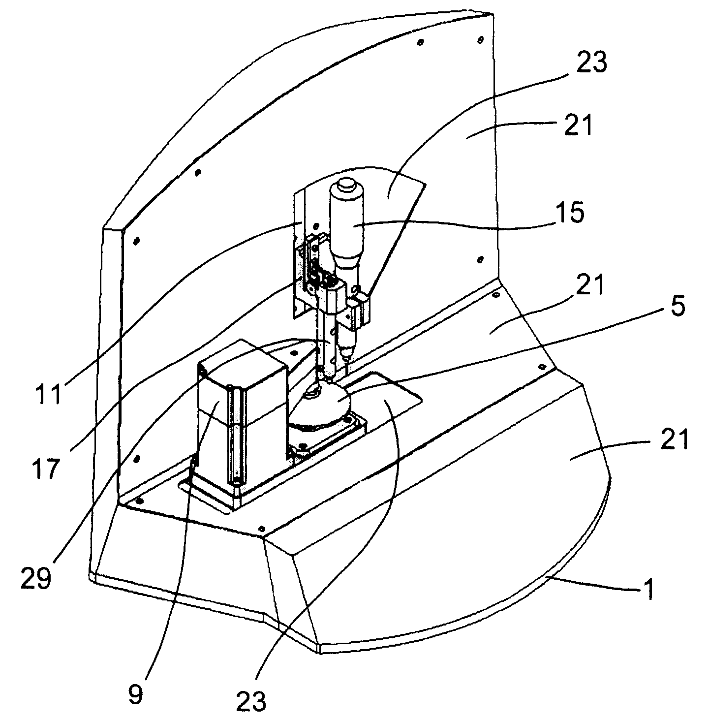
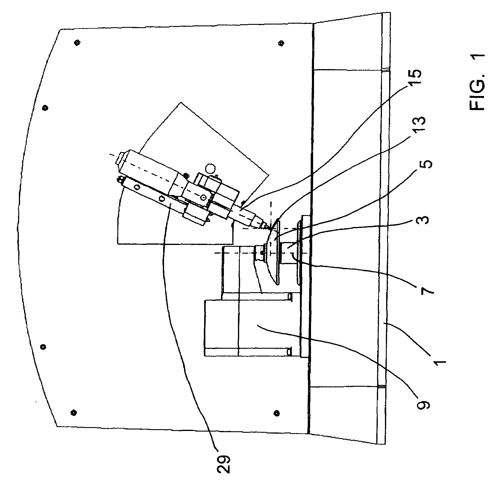
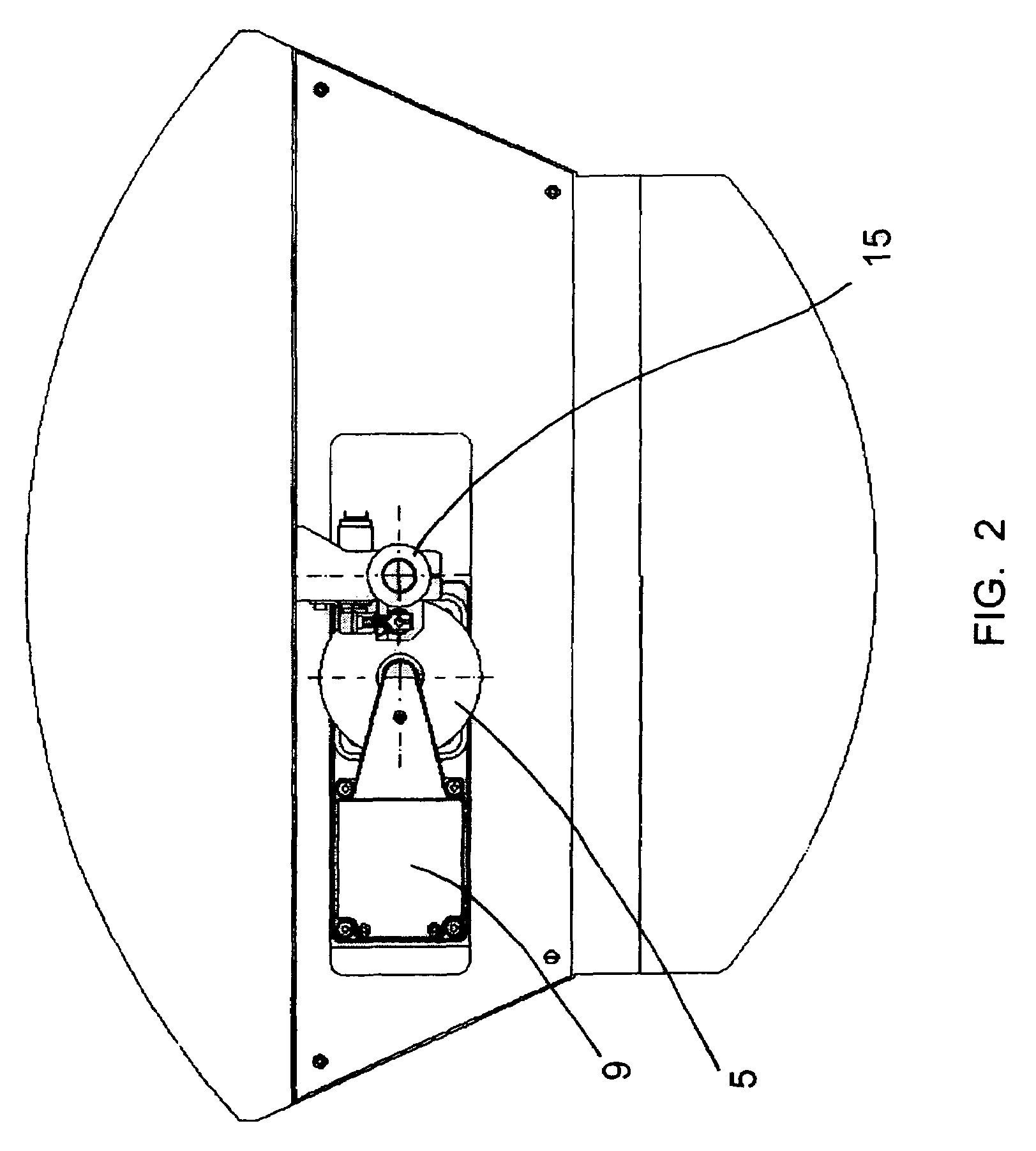
[0039]In FIGS. 1-4, it is shown a numeric control bore according to the invention. The bore has a support bedplate 1, on which attachment means 3 are mounted, clamping lens 5 so that its lens plane is substantially horizontal. The attachment means 3 comprise a suction pad and an attachment axis protruding from said suction pad and which, in a known way by a person skilled in the art, allows to define the position and the attachment angle of the suction pad with respect to the lens 5. The attachment means 3 form an C-shaped arch and lens 5 is fixed between their open ends, rotatable about the first upright rotating axis 7 coinciding with the attachment axis of the suction pad. Thanks to the rotation means 9 lens 5 can be rotated about the first rotating axis 7 as required. In this way, it is possible to determine the angle position of lens 5 at any moment, constituting the first degree of freedom of the bore.

[0040]The assembly formed by the attachment means 3 and the rotation means 9...


PUM

PropertyMeasurementUnit
anglesaaaaaaaaaa
degree of freedomaaaaaaaaaa

Abstract

Numeric control bore for boring an eyeglass lens and corresponding method. The bore comprises a bedplate (1), attachment device (3) for the lens (5), rotation device (9) for the lens (5) according to a first axis (7) (first degree of freedom), and a support column (11) with a head (15), wherein the attachment device (3) and the support column (11) can be moved between each other (second degree of freedom). The support column (11) has a first end linked to the bedplate (1) being capable of rotating about a second end (third degree of freedom) and the head (15) is linked to the column (11) by translation structure (fourth degree of freedom). The apparatus only has these four degrees of freedom in order to fix the relative position between the head (15) and the lens (5).

Description

FIELD OF THE INVENTION[0001]This invention relates to a numeric control bore for boring an eyeglass lens and a machining method of an eyeglass lens.STATE OF THE ART[0002]The numeric control bores for boring eyeglass lenses are known. Often the eyeglass lenses have holes, wherein various elements are inserted, as bridges, rods, etc. This is particularly the case of the so-called “without frame” or “airframes”. In these cases, the lens is not wrapped by a structure to which the rods and the connection jumper are mounted between both lenses but these elements are mounted, for example, by means of screws, directly to the lenses. To this end, it is necessary to pierce holes in the lens, wherein the corresponding screws can be inserted.[0003]The Spanish patent ES 2.133.828, published on 1st May 1998, discloses an apparatus for polishing, boring, cutting and welding eyeglass lenses. This apparatus has a machining head comprising an apparatus generating a beam of laser rays or an electron b...

Claims


Application Information

Patent Timeline
Patent Type & Authority Patents(United States)
IPC IPC(8): B23P23/00B23B39/00B23C3/16B23B41/00B23Q1/48B23Q17/22B24B9/14B24B47/22B28D1/14
CPCB28D1/143Y10T408/93Y10T29/49996Y10T29/5107Y10T408/563Y10T409/307672Y10T408/561Y10T408/5614B24B13/00
Inventor ALBERT SESENA, SANTIAGOFRUCTUOSO GONZALEZ, SERGIOPEREZ RIBERA, CARLOS
Owner INDO INT
Why Eureka
Try Eureka