Method and device for performing stereoscopic image display based on color selective filters

a color selective filter and stereoscopic image technology, applied in stereoscopic photography, instruments, optics, etc., can solve the problems of color artifacts appearing in projected images, obscuration devices often tend to disappear,

Inactive Publication Date: 2007-06-07
INFITEC
View PDF24 Cites 185 Cited by
  • Summary
  • Abstract
  • Description
  • Claims
  • Application Information

AI Technical Summary

Benefits of technology

[0024] The filters which filter a parameter of the light in a color selective manner of the first and the second passive stereo projection device may have overlapping regions in their spectral characteristic. This is advantageous, as less restringing requirements need to be set on the filters.

Problems solved by technology

Obscuration devices often tend to disappear, which is very annoying in case they are rather expensive, but does not really matter in case they are e.g. a cheap pair of glasses with colored plastic filters as the lenses.
However, it is a disadvantage of the method of DE-199 24 167 that very steep filters are required, which are difficult to implement, and that, due to differences in wavelengths for the colors shown to each eye, color artifacts appear in the projected images.

Method used


Image

  • Method and device for performing stereoscopic image display based on color selective filters
  • Method and device for performing stereoscopic image display based on color selective filters
  • Method and device for performing stereoscopic image display based on color selective filters

Examples


embodiment 1

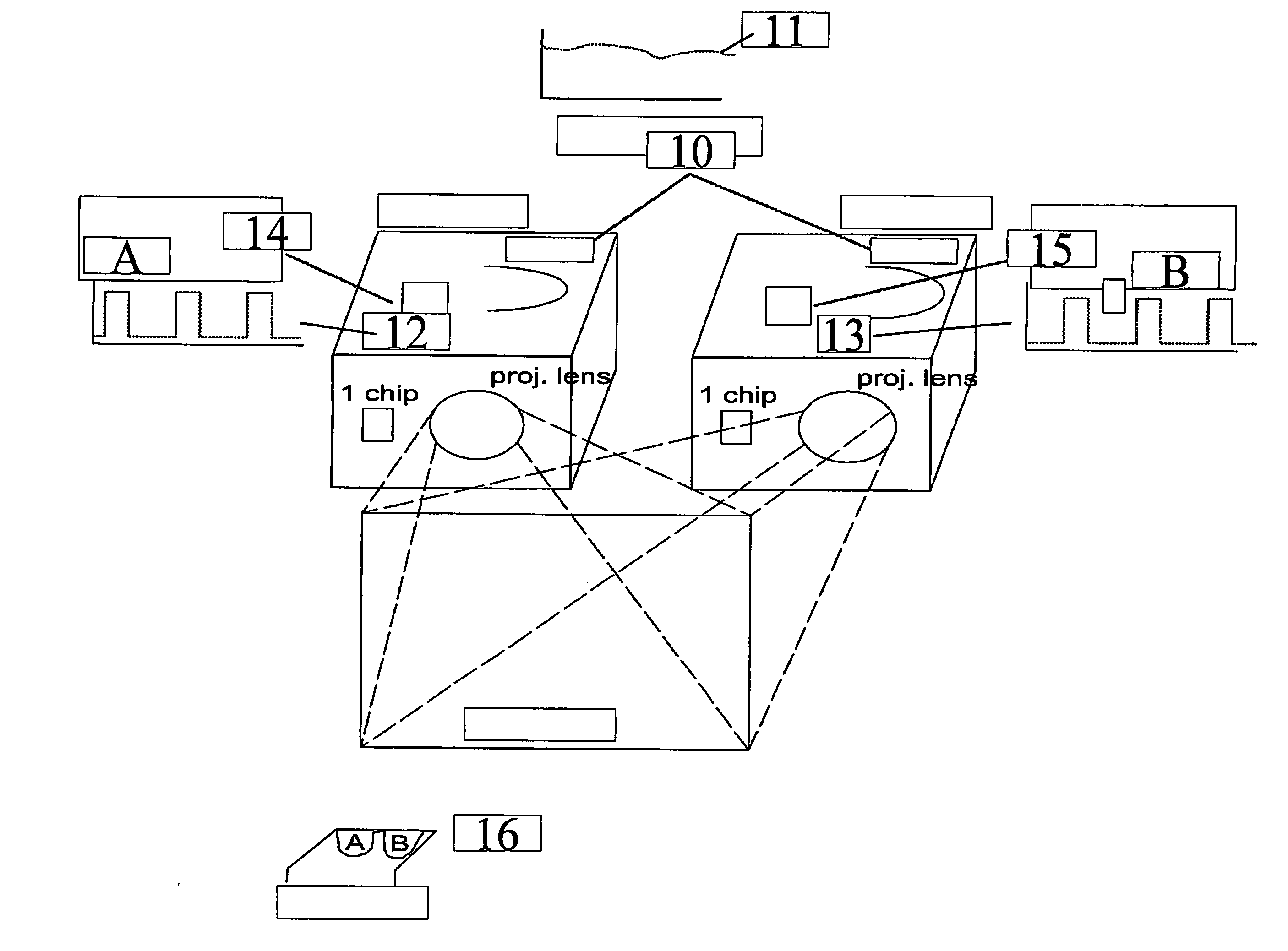
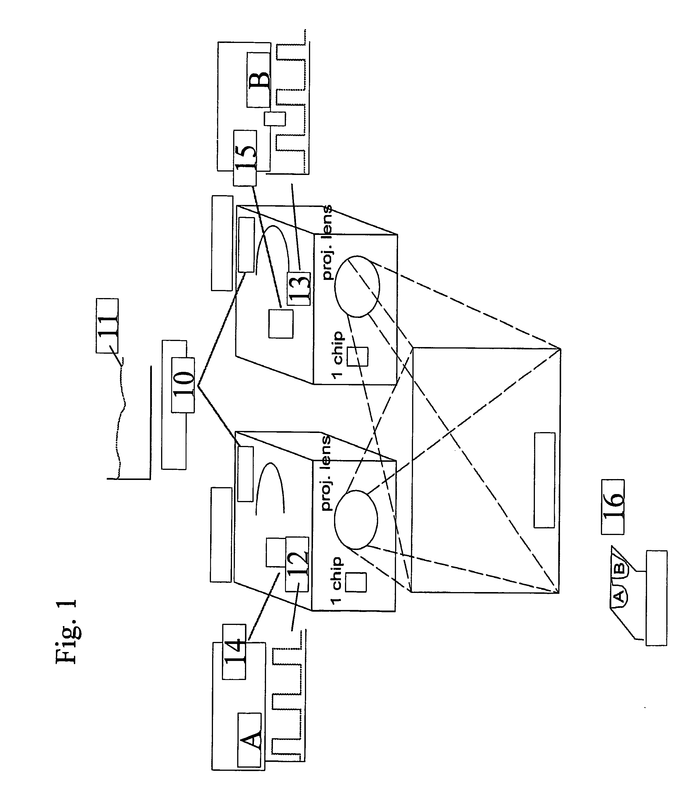
[0053] Single chip digital light processing (DLP™)products are currently popular as low price alternatives for 3-chip DLP and liquid crystal display (LCD) products. In single chip DLP projectors the image is created by one Digital Mirror Device (DMD) and the color is added by shining the reflected light through a spinning multi segment color wheel. By using DLP Technology, projectors can be made lighter in weight and smaller in design while also producing contrast ratio's of up to 2000:1 and beyond. Mercury-based high pressure short arc lamps, such as e.g. Ultra High Performance (UHP™) lamps obtainable from Philips, or Super High Pressure (SHP) lamps obtainable from Mitsubishi, are commonly used in these applications due to budget constraints. The spectrum of these lamps is characterized by huge peaks and a modest continuum, despite the high pressure.

[0054] Despite the budgetary advantages of the above described family of lamps for single chip projectors, it is preferable, although...

embodiment 2

[0060] In three chip DLP products, Texas Instruments supports bit sequences suitable for 3D projection, where images for the left eye and for the right eye are successively projected onto a single display device. In addition, some viewing tools with active or passive shutter means (e.g. glasses, lenses) are needed to discriminate images intended to be viewed by one eye from images intended to be viewed by the other.

[0061] In the prior art this may be done by using a product called Z-screen® from Stereographics Company, California, but this product uses polarization to separate the two images, which leads to a lower stereoscopic quality than if a color selection method would be used like it is explained in the text below, due to a higher cross-talk between the image for left and right eye. Furthermore, stereo defined by polarization requires non-depolarizing screens (or lowly-depolarizing ones) both for front and retro projection. In that case one is limited to high gain screens (i....

embodiment 3

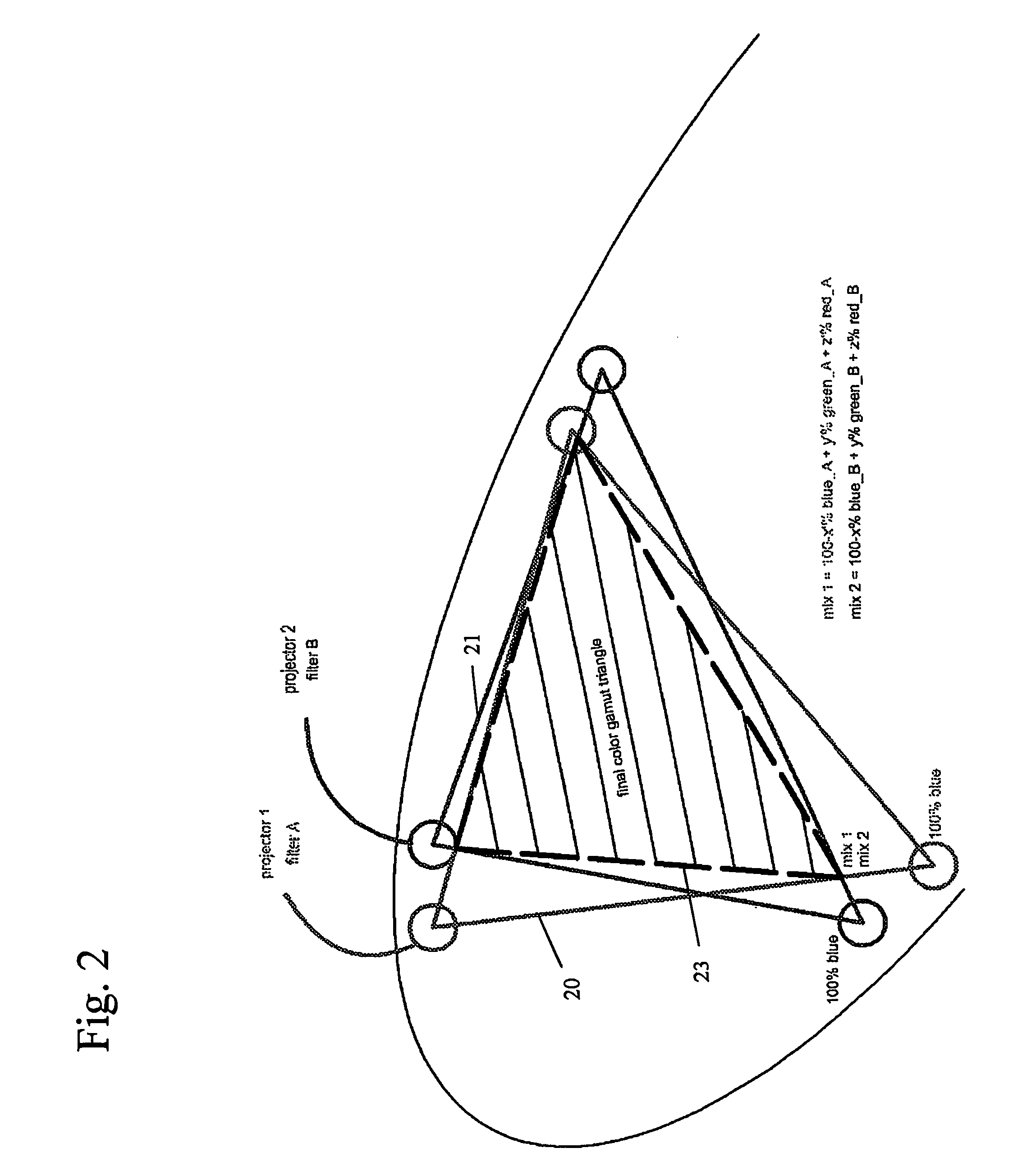
[0079] This embodiment relates to the use of filters which filter a parameter of the light in a color selective manner, e.g. color selective filters, with mutual overlap, combined with polarization filters. With “filters which filter a parameter of the light in a color selective manner” in this and other embodiments is meant any suitable optical filter which filters amplitude, frequency or polarisation of the light in a color selective manner. A “filter which filters amplitude of the light in a color selective manner” is typically known as a color selective filter; i.e. a filter which transmits some wavelengths or wavelength bands of light impinging onto it, and filtering out, i.e. reflecting and / or absorbing other wavelenghts or wavelength bands of light This type of filter includes optical low pass filters, optical high pass filters or optical band pass filters. A “filter which filters polarisation of the light in a color selective manner” is typically known as a color selective r...


PUM


Abstract

In one aspect, the present invention relates to a stereoscopic projection system including a projection device with at least one filter which filters a parameter of the light in a color selective manner. The at least one filter which filters a parameter of the light in a color selective manner has a spectral characteristic for transmitting light in a first wavelength band or set of wavelength bands and for reflecting light in a second wavelength band or set of wavelength bands. The projection device includes a device, such as e.g. a rotating wheel or a sliding filter, for fast synchronized switching between light in different wavelength bands or sets of wavelength bands. In a further aspect, a stereoscopic projection system is provided in which a combination of a first and a second filter mechanism are used, the first filter mechanism being a filter which filters a parameter of the light in a color selective manner, such as a color selective filter or a color selective retarder, and the second filter mechanism preferably being a polarizer or a shutter.

Description

TECHNICAL FIELD OF THE INVENTION [0001] The present invention relates to methods and apparatus for stereoscopic image display, for example stereoscopic projection, as well as control methods and controllers therefor. BACKGROUND OF THE INVENTION [0002] Humans and many animals have binocular vision provided by two eyes which look in the same direction. Two parallel aligned but spaced eyes deliver two slightly different images of the same scene. This is due to the 4 to 6 cm separation between the eyes, which makes each eye have a slightly different viewpoint. The images from these two different viewpoints are sent to the brain, and this difference, which is termed parallax, is interpreted as depth. The nearer an object is to the eyes, the greater the difference between the two images. From the difference between the two images, the brain can display an impression of depth. [0003] Stereoscopic image displays, such as stereoscopic projection for example, are based on the same principle: ...

Claims


Application Information

Patent Timeline
Patent Type & Authority Applications(United States)
IPC IPC(8): G02B27/26G02B30/25G03B35/26H04N13/363
CPCG02B26/007H04N13/0427H04N13/0431H04N13/0434H04N13/0438H04N13/0459H04N13/337H04N13/341H04N13/334H04N13/363H04N13/365G02B30/23
Inventor MAXIMUS, BARTMALFAIT, KOENVERMEIRSCH, KOENRAAD
Owner INFITEC
Why Eureka
Try Eureka