Lithographic apparatus and device manufacturing method
What is AI technical title?
AI technical title is built by Patsnap AI team. It summarizes the technical point description of the patent document.
a technology of lithographic projection and manufacturing method, which is applied in the direction of electrical apparatus, printers, instruments, etc., can solve the problems of unfavorable and unpredictable effects, problems in subsequent processing of substrates, etc., and achieve the effect of reducing residual liquid
Active Publication Date: 2008-04-01
ASML NETHERLANDS BV
View PDF187 Cites 186 Cited by
Summary
Abstract
Description
Claims
Application Information
AI Technical Summary
This helps you quickly interpret patents by identifying the three key elements:
Problems solved by technology
Method used
Benefits of technology
Benefits of technology
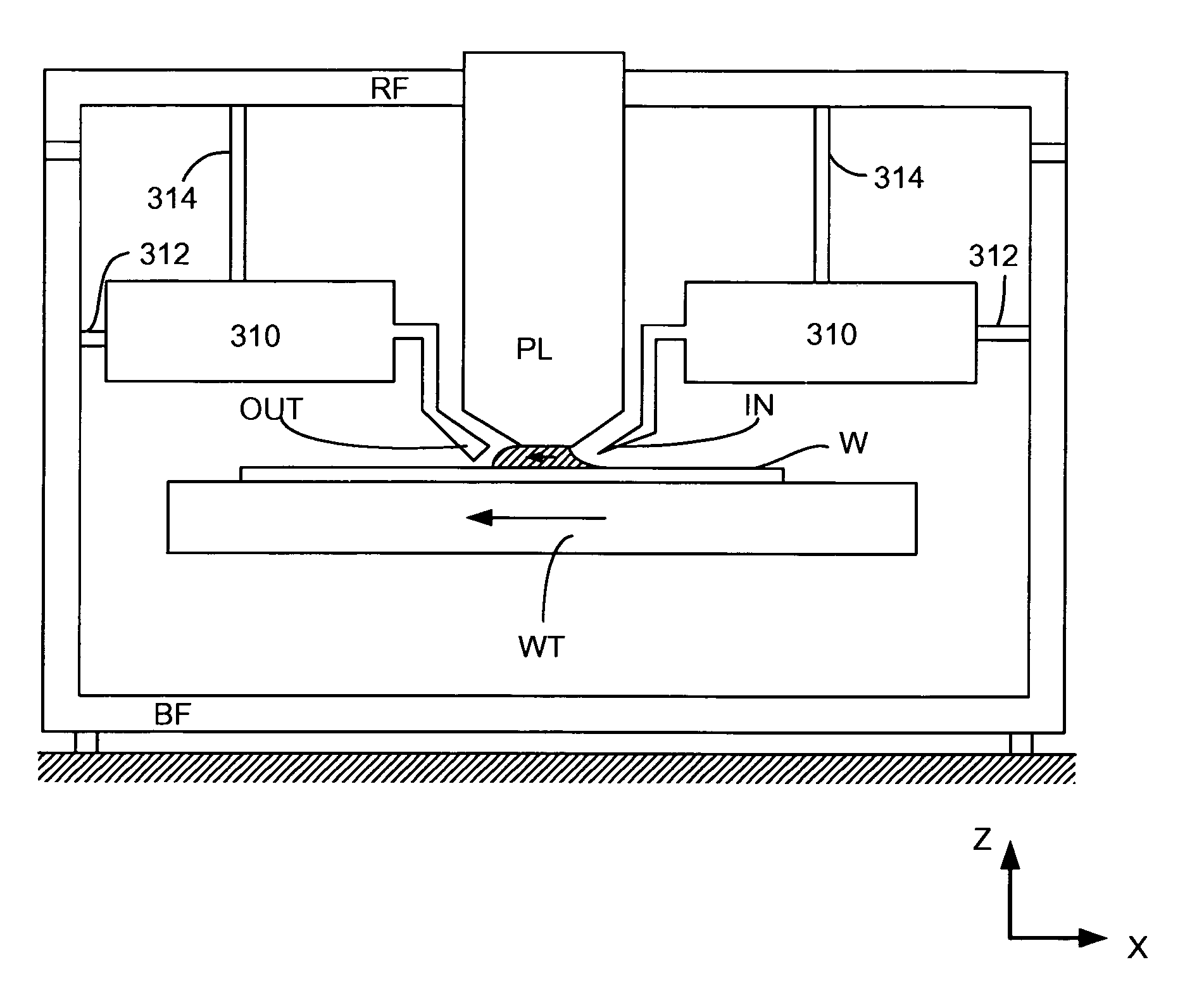
The present invention relates to a lithographic projection apparatus that reduces the residual liquid left on a substrate after exposure. The invention includes a liquid supply system that moves relative to the substrate to accommodate changes in the surface height of the substrate. The liquid supply system can move in the direction of the optical axis and rotate about axes perpendicular to the optical axis. The actuator can adjust the height and tilt of the liquid supply system to accommodate the substrate's surface height. The control system can use a feedback control method to maintain the predetermined height of the liquid supply system. The invention also includes a sensor to measure the height of the substrate and a reference frame to support the projection system. The invention can be used in the manufacture of ICs, integrated optical systems, guidance and detection patterns for magnetic domain memories, LCDs, thin-film magnetic heads, etc.
Problems solved by technology
This requires additional and / or more powerful motors and turbulence in the liquid may lead to undesirable and unpredictable effects.
This liquid can cause problems in subsequent processing of the substrate.
Method used
Image
Click on the blue label to locate the original text in one second.
Reading with bidirectional positioning of images and text.
Examples
Embodiment Construction
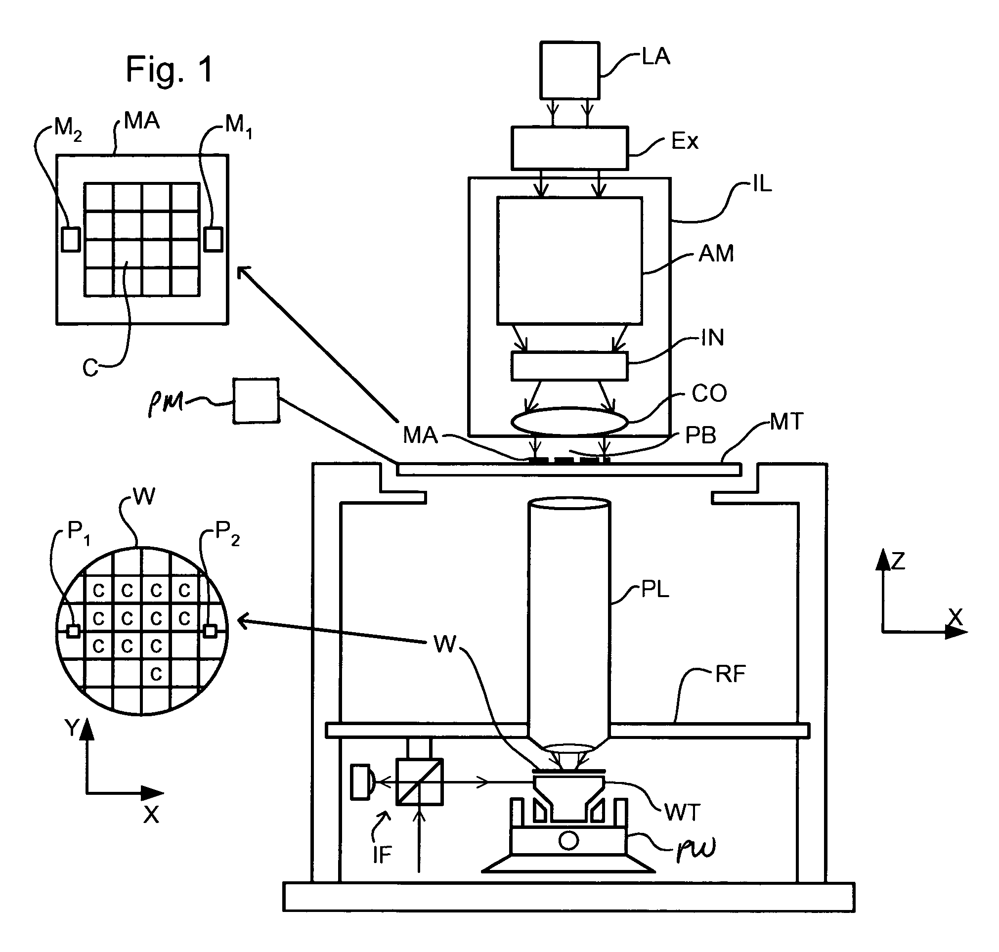
[0041]FIG. 1 schematically depicts a lithographic apparatus including an illumination system (illuminator) IL configured to provide a beam PB of radiation (e.g. UV radiation). A first support (e.g. a mask table) MT is configured to support a patterning device (e.g. a mask) MA and is connected to a first positioning device PM that accurately positions the patterning device with respect to a projection system PL. A substrate table (e.g. a wafer table) WT is configured to hold a substrate (e.g. a resist-coated wafer) W and is connected to a second positioning device PW that accurately positions the substrate with respect to the projection system PL. The projection system (e.g. a refractive projection lens) PL is configured to image a pattern imparted to the beam PB by the patterning device MA onto a target portion C (e.g. including one or more dies) of the substrate W.
[0042]As here depicted, the apparatus is of a transmissive type (e.g. employing a transmissive mask). Alternatively, th...
PUM
Property
Measurement
Unit
height
aaaaa
aaaaa
wavelength
aaaaa
aaaaa
wavelength
aaaaa
aaaaa
Abstract
In a lithographic apparatus, a localized area of the substrate surface under a projection system is immersed in liquid. The height of a liquid supply system above the surface of the substrate can be varied using actuators. A control system uses feedforward or feedback control with input of the surface height of the substrate to maintain the liquid supply system at a predetermined height above the surface of the substrate.
Description
[0001]This application claims priority to European Patent Applications 03252955.4 and 03256643.2, filed May 13, 2003 and Oct. 22, 2003, respectively, the contents of both applications incorporated herein by reference.BACKGROUND OF THE INVENTION[0002]1. Field of the Invention[0003]The present invention relates to a lithographic projection apparatus and a device manufacturing method.[0004]2. Description of the Related Art[0005]A lithographic apparatus is a machine that applies a desired pattern onto a target portion of a substrate. Lithographic apparatus can be used, for example, in the manufacture of integrated circuits (ICs). In that circumstance, a patterning device, such as a mask, may be used to generate a circuit pattern corresponding to an individual layer of the IC, and this pattern can be imaged onto a target portion (e.g. including part of one, or several, dies) on a substrate (e.g. a siliconwafer) that has a layer of radiation-sensitive material (resist). In general, a sin...
Claims
Application Information
Patent Timeline
Application Date:The date an application was filed.
Publication Date:The date a patent or application was officially published.
First Publication Date:The earliest publication date of a patent with the same application number.
Issue Date:Publication date of the patent grant document.
PCT Entry Date:The Entry date of PCT National Phase.
Estimated Expiry Date:The statutory expiry date of a patent right according to the Patent Law, and it is the longest term of protection that the patent right can achieve without the termination of the patent right due to other reasons(Term extension factor has been taken into account ).
Invalid Date:Actual expiry date is based on effective date or publication date of legal transaction data of invalid patent.
InventorSTREEFKERK, BOBBAKKER, LEVINUS PIETERBASELMANS, JOHANNES JACOBUS MATHEUSCOX, HENRIKUS HERMAN MARIEDERKSEN, ANTONIUS THEODORUS ANNA MARIADONDERS, SJOERD NICOLAAS LAMBERTUSHOOGENDAM, CHRISTIAAN ALEXANDERLOF, JOERILOOPSTRA, ERIK ROELOFMERTENS, JEROEN JOHANNES SOPHIA MARIAVAN DER MEULEN, FRITSMULKENS, JOHANNES CATHARINUS HUBERTUSVAN NUNEN, GERARDUS PETRUS MATTHIJSSIMON, KLAUSSLAGHEKKE, BERNARDUS ANTONIUSSTRAAIJER, ALEXANDERVAN DER TOORN, JAN-GERARD CORNELISHOUKES, MARTIJN

