Method and controller for exhaust gas temperature control

a technology of exhaust gas and temperature control, which is applied in the direction of electrical control, machines/engines, mechanical equipment, etc., can solve the problems of insufficient response of control to changes in exhaust gas temperature, insufficient speed and accuracy of control of exhaust gas temperature, and insufficient accuracy of exhaust gas temperature control. , to achieve the effect of sufficient speed and accuracy, accurate control of exhaust gas temperature, and sufficient accuracy

Active Publication Date: 2006-10-31
ROBERT BOSCH GMBH
View PDF6 Cites 10 Cited by
  • Summary
  • Abstract
  • Description
  • Claims
  • Application Information

AI Technical Summary

Benefits of technology

[0010]These measures provide an exhaust gas temperature control system that responds to changes in the exhaust gas temperature with sufficient speed and accuracy even during transient operating conditions. In the process, the accuracy of the exhaust gas temperature control is ensured by the first, outer control loop, which processes an actual value for a temperature downstream of the upstream catalyst as an input variable. This allows the temperature requirements of a downstream particulate filter or catalyst to be met with sufficient accuracy during steady-state conditions. Sufficient response speed of the control system is achieved by the parallel processing of a second actual value that is used as a measure of a temperature upstream of the upstream catalyst. The time variation of this second actual value is not influenced by the heat capacity of the upstream catalyst which, in a way acts, as a low-pass filter for changes in the exhaust gas temperature. The totality of these features provides an exhaust gas control system that produces sufficiently accurate and sufficiently fast control actions even during transient operating conditions, during which the exhaust gas temperatures can vary strongly.

Problems solved by technology

This makes control of the exhaust gas temperature at the inlet of the particulate filter so sluggish that the response of the control to changes in the exhaust gas temperature is only fast enough when the internal combustion engine is in steady-state operation.
Because of this, proper regeneration of the particulate filter during normal operation of the motor vehicle becomes more difficult.

Method used


Image

  • Method and controller for exhaust gas temperature control
  • Method and controller for exhaust gas temperature control
  • Method and controller for exhaust gas temperature control

Examples


Embodiment Construction

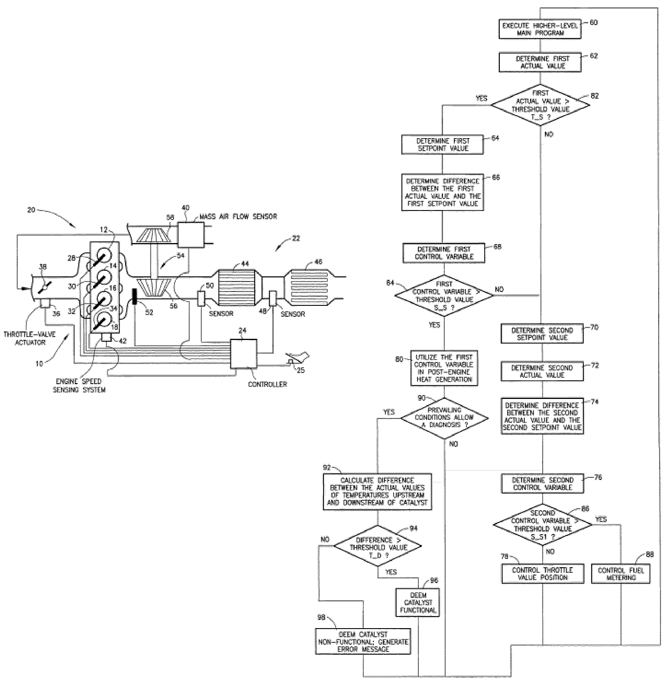
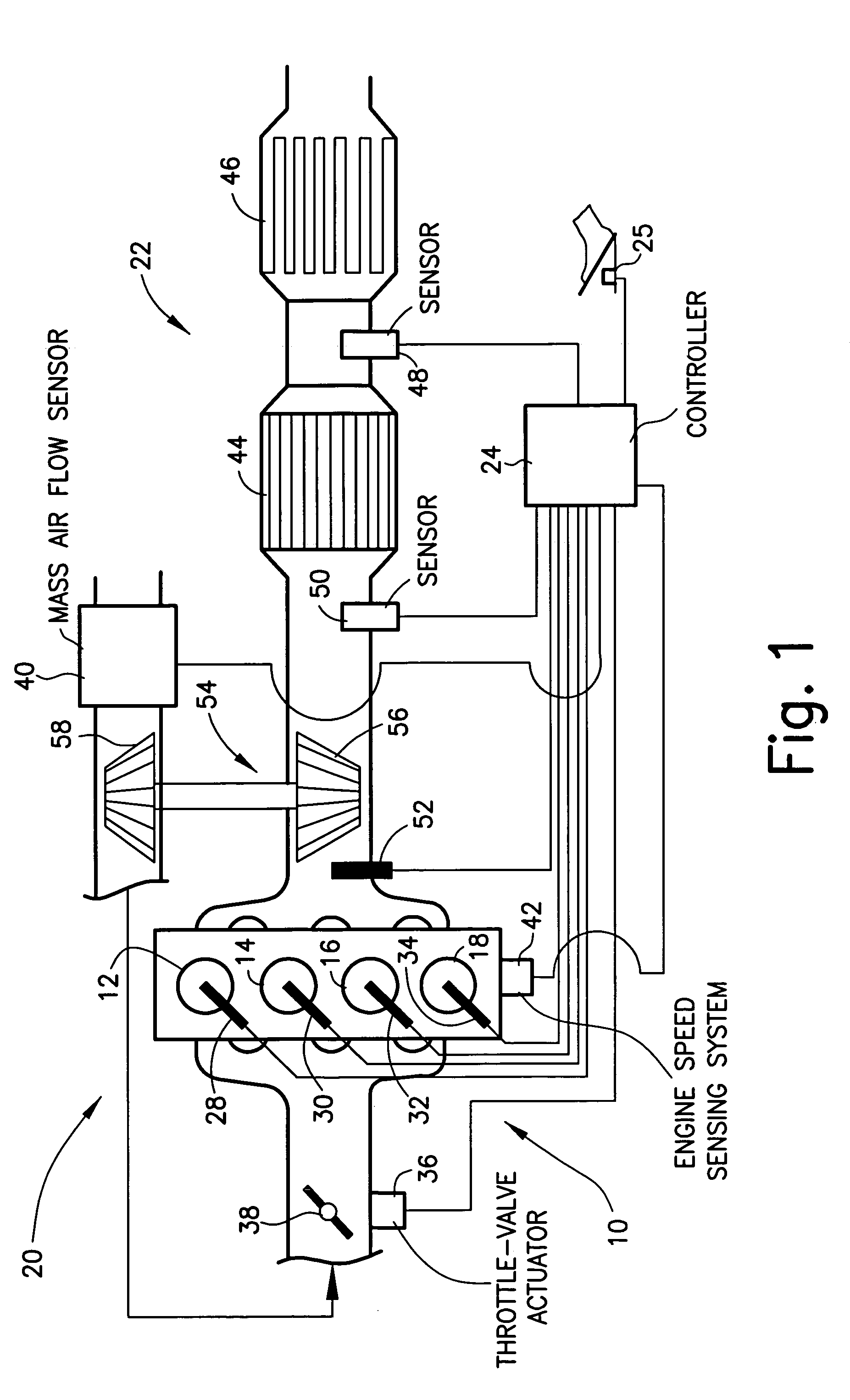
[0043]FIG. 1 shows an internal combustion engine 10 having combustion chambers 12, 14, 16, 18, an intake pipe 20, and an exhaust gas aftertreatment system 22. Internal combustion engine 10 is controlled by a controller 24 which, especially, but not exclusively, receives the signal of a driver command sensor 25 for that purpose. Controller 24 uses the input signals to form control signals for final control elements of internal combustion engine 10. In particular, for example, controller 24 calculates fuel injection pulse widths used for opening fuel injectors 28, 30, 32, 34; each of fuel injectors 28, 30, 32, 34 injecting fuel into a specific combustion chamber 12, 14, 16, 18. The quantity of intake air flowing into internal combustion engine 10 is controlled by controller 24, possibly by driving a throttle-valve actuator 36 which controls the position of a throttle valve 38 located in intake pipe 20. The intake air mass flow rate is measured by a mass air flow sensor 40 and transmit...


PUM


Abstract

Described is a method for controlling a temperature downstream of a catalyst in the exhaust tract of an internal combustion engine including a first control loop in which a first control variable is calculated from a first deviation that is calculated from a first actual value and a first setpoint value and influences an intra-engine heat generation. In the process, the first actual value is determined as a measure of a temperature downstream of the catalyst. The method features a second control loop in which at least one second control variable is calculated from a second deviation that is calculated from a second actual value and a second setpoint value; a temperature upstream of the catalyst being determined as the second actual value. Also described is a controller which controls the sequence of such a method.

Description

FIELD OF THE INVENTION[0001]The present invention relates to a method for controlling a temperature downstream of a catalyst in the exhaust tract of an internal combustion engine including a first, outer control loop in which a first control variable is calculated from a first deviation that is calculated from a first actual value and a first setpoint value; a measure of a temperature downstream of the catalyst being determined as the first actual value.BACKGROUND INFORMATION[0002]The present invention further relates to a controller for controlling a temperature downstream of a catalyst in the exhaust tract of an internal combustion engine including a first, outer control loop in which the controller calculates a first control variable from a first deviation that is calculated by the controller from a first actual value and a first setpoint value; a measure of a temperature downstream of the catalyst being used as the first actual value.[0003]Such a method and controller are descri...

Claims


Application Information

Patent Timeline
Patent Type & Authority Patents(United States)
IPC IPC(8): F01N3/00F01N3/10F01N3/035F02D45/00F01N3/20F01N3/24F02B37/00F02D41/02F02D41/14F02D41/22F02D41/38F02D41/40
CPCF01N3/035F02D41/0275F02D41/1441F02D41/1446F01N3/20F01N2430/085F02B37/00F02D41/22F02D41/405
Inventor PFAEFFLE, ANDREASWUEST, MARCELSAMUELSEN, DIRKFORTHMANN, STEFANKOLITSCH, MICHAELFRITSCH, ANDREAS
Owner ROBERT BOSCH GMBH
Why Eureka
Try Eureka