Drive device for stepper motor and indicating apparatus using the same

a technology of indicating apparatus and drive device, which is applied in the direction of motor/generator/converter stopper, electric programme control, dynamo-electric converter control, etc., can solve the problem that non-conformity may give the driver a sense of discomfort, and achieve the effect of efficient switching

Active Publication Date: 2006-10-31
YAZAKI CORP
View PDF12 Cites 7 Cited by
  • Summary
  • Abstract
  • Description
  • Claims
  • Application Information

AI Technical Summary

Benefits of technology

[0008]It is therefore an object of the present invention to provide a drive device for stepper motors and an indicating apparatus using the drive device capable of efficiently switching between the zero-position detection process operation of a plurality of stepper motors and normal operation.
[0016]In the above configuration, the drive device is capable of efficiently switching between the zero-position detection operation and normal operation in the plurality of stepper motors.
[0020]In the above configuration, the drive device is capable of efficiently switching between the zero-position detection operation and normal operation in the plurality of stepper motors.
[0026]In the above configuration, the zero-position detection operation can be restored quickly to the normal operation.

Problems solved by technology

As the tachometer operates not to give any indication of the number of revolutions of the engine immediately after the engine is started in the case described above, this nonconformity may give the driver a sense of discomfort.

Method used


Image

  • Drive device for stepper motor and indicating apparatus using the same
  • Drive device for stepper motor and indicating apparatus using the same
  • Drive device for stepper motor and indicating apparatus using the same

Examples


Embodiment Construction

[0034]An embodiment of the invention will now be described by reference to the drawings.

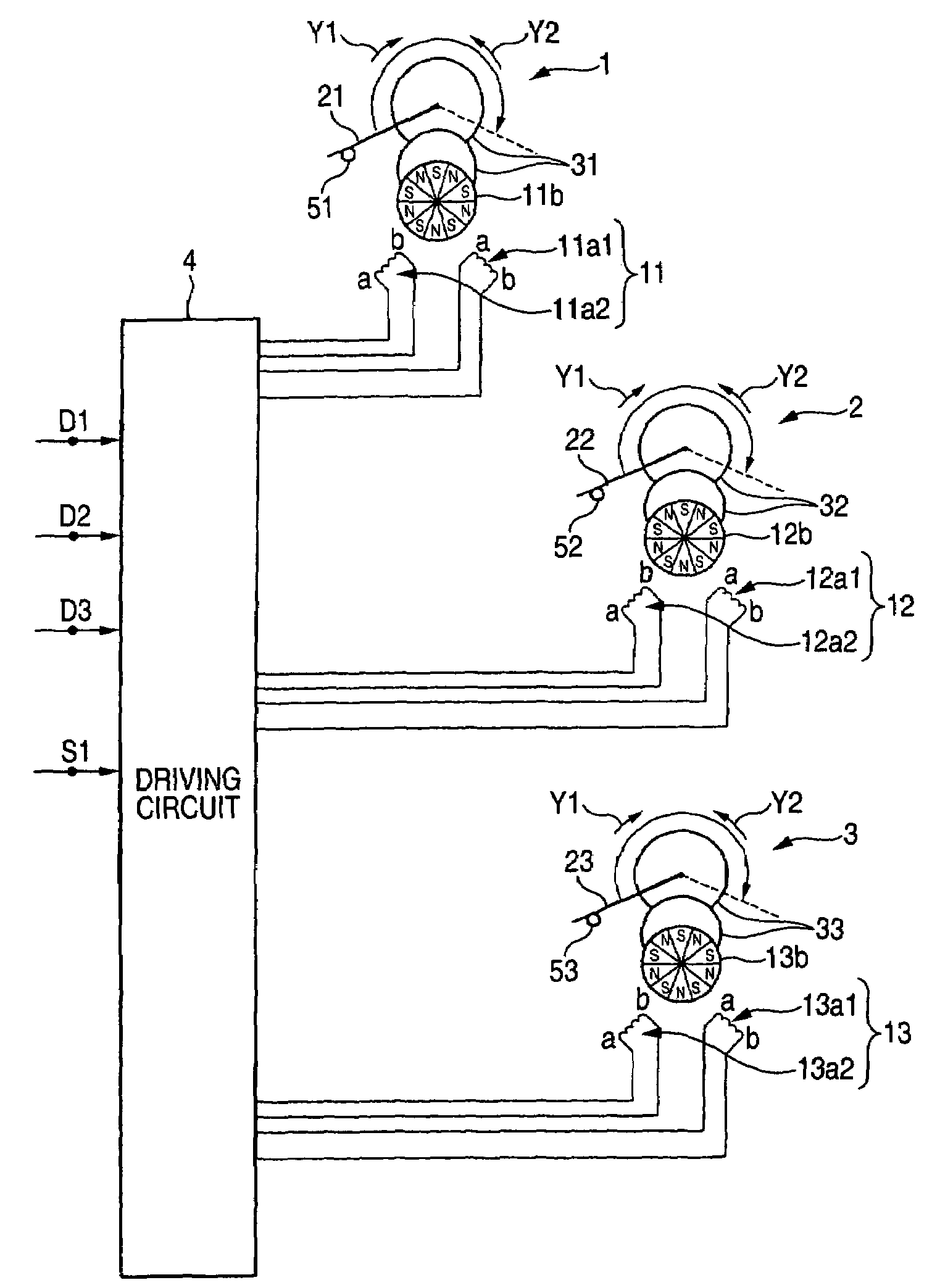
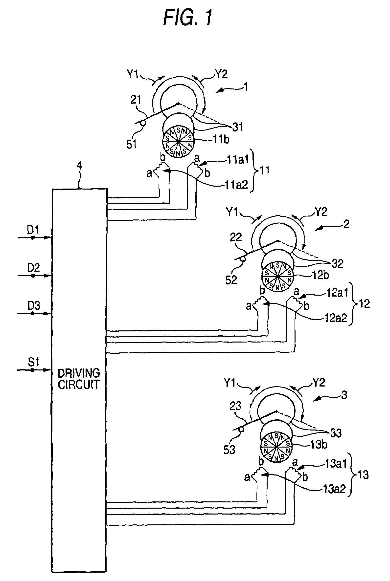
[0035]FIG. 1 is a diagram showing an indicating apparatus incorporating a drive device for driving stepper motors according to the embodiment of the invention. The indicating apparatus serves as an on-board combination meter including a tachometer 1, a fuel meter 2 and a speedometer 3. For example, the meters 1, 2 and 3 have corresponding stepper motors 11, 12 and 13. The stepper motors 11, 12 and 13 respectively have a pair of excitation coils 11a1 and 11a2, a pair of excitation coils 12a1 and 12a2 and a pair of excitation coils 13a1 and 13a2, and rotors 11b, 12b and 13b, each having and being magnetized by five sets of N and S magnetic poles alternately arranged, which are rotated by following variations in the excitation state of the pairs of excitation coils 11a1 and 11a2, 12a1 and 12a2 and 13a1 and 13a2.

[0036]Further, the indicating apparatus includes a plurality of pointers 21, 22 and 23 as...


PUM


Abstract

A drive device includes stepper motors, each having an excitation coil and a rotor rotating based on variation in the excitation state of the excitation coil; driven members, each moving in accordance with the rotation of the rotor of the corresponding stepper motor; stoppers, each stopping the driven member mechanically at a zero position; and a controller, controlling the respective stepper motors so as to selectively performs either a normal operation in which the stepper motor is driven so as to rotate, or a zero-position detection operation in which the stepper motor is driven so that the driven member is moved to the stopper. The controller starts to perform the zero-position detection operation simultaneously in all of the stepper motors and changes the stepper motor which has terminated the zero-position detection operation to the normal operation without waiting for the termination of the zero-position detection operation in other stepper motors.

Description

BACKGROUND OF THE INVENTION[0001]The present invention relates to a drive device for stepper motors applicable to an on-board combination meter and so on and to an indicating apparatus using the drive device.[0002]For example, JP-A-2001-327193 discloses a drive device for controlling the driving of a plurality of stepper motors for use in a tachometer, a fuel meter and so on in an on-board combination meter of the sort mentioned above. The drive device includes a plurality of stepping motors, a plurality of driven members, a plurality of stoppers, a plurality of first excitation members, a plurality of second excitation members, a plurality of detection coils, a position detection member, and control member. Each of the stepping motors has a plurality of excitation coils as well as a rotor magnetized to have N and S magnetic poles and is rotated by following variations in the excitation state of the excitation coils. The driven members moves in response to the rotating operation of ...

Claims


Application Information

Patent Timeline
Patent Type & Authority Patents(United States)
IPC IPC(8): G05B19/40H02P1/18G01D11/00H02K7/10H02K11/00H02P5/46H02P8/00H02P8/08H02P8/38H02P8/40
CPCH02P8/08H02P8/40G01D2213/10
Inventor OISHI, MASAKIUMEHARA, HIDEMASA
Owner YAZAKI CORP
Why Eureka
Try Eureka