Method for braking a vessel with two marine propulsion devices

a technology of propulsion device and braking device, which is applied in the direction of marine propulsion, special-purpose vessels, vessel construction, etc., can solve the problems of significant cavitation and adverse effects on the efficiency of the braking force caused by the reverse propeller

Inactive Publication Date: 2006-11-07
BRUNSWICK CORPORATION
View PDF15 Cites 53 Cited by
  • Summary
  • Abstract
  • Description
  • Claims
  • Application Information

AI Technical Summary

Benefits of technology

[0026]In certain embodiments of the present invention, it can further comprise the step of determining a rate of movement of a throttle control device, such as a manually operated throttle handle, from an initial forward marine vessel velocity command to a current marine vessel velocity command. These velocity commands are represented by physical positions of the throttle handle before and after the operator moves the handle for the purpose of stopping the forward velocity of the marine vessel. The selecting step can comprise a plurality of selections of angular magnitudes which are sequentially selected as a function of changing magnitudes of the velocity

Problems solved by technology

When propellers are suddenly reversed, significant cavitation often occurs and the ef

Method used


Image

  • Method for braking a vessel with two marine propulsion devices
  • Method for braking a vessel with two marine propulsion devices
  • Method for braking a vessel with two marine propulsion devices

Examples


Embodiment Construction

[0034]Throughout the description of the preferred embodiment of the present invention, like components will be identified by like reference numerals.

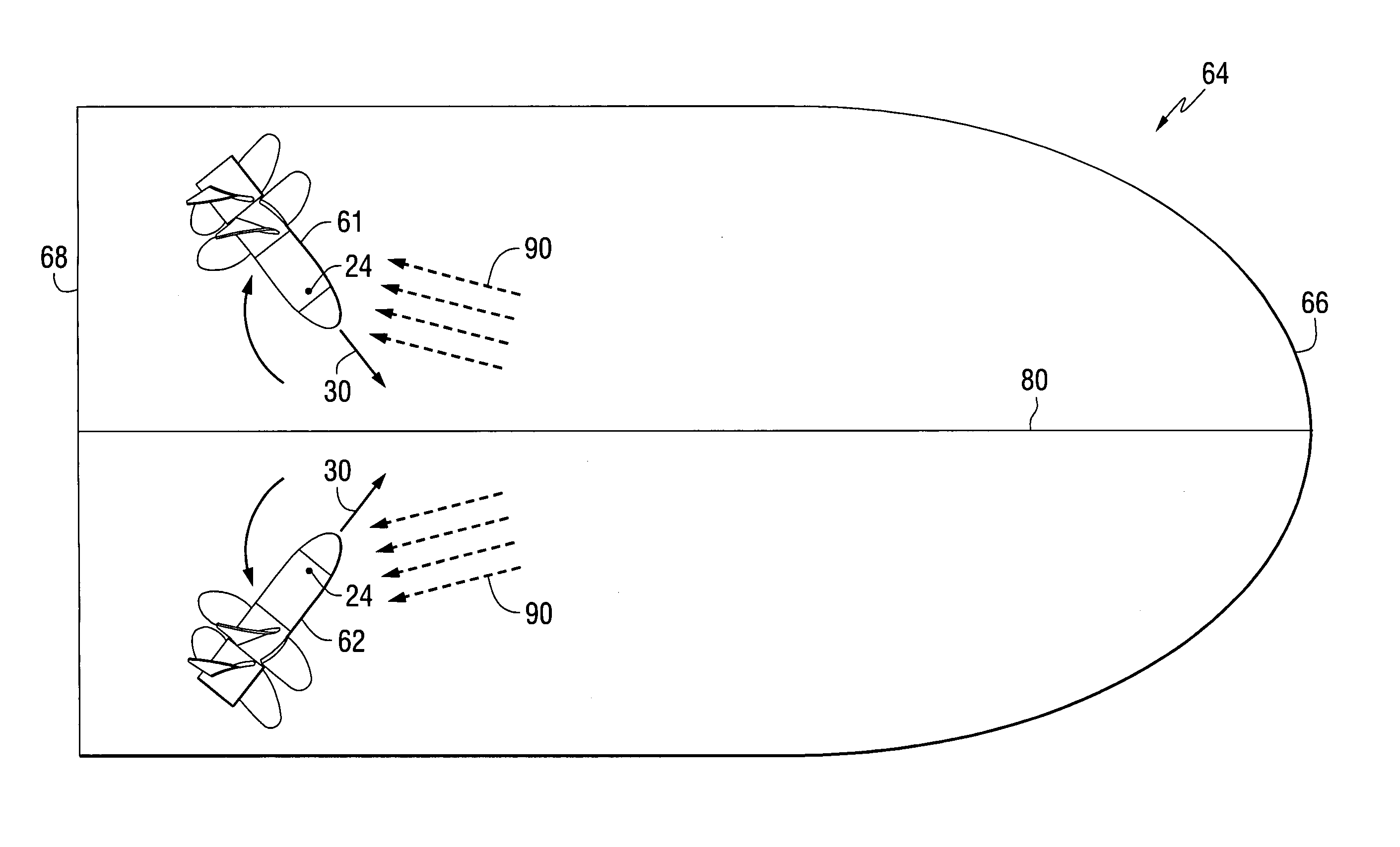
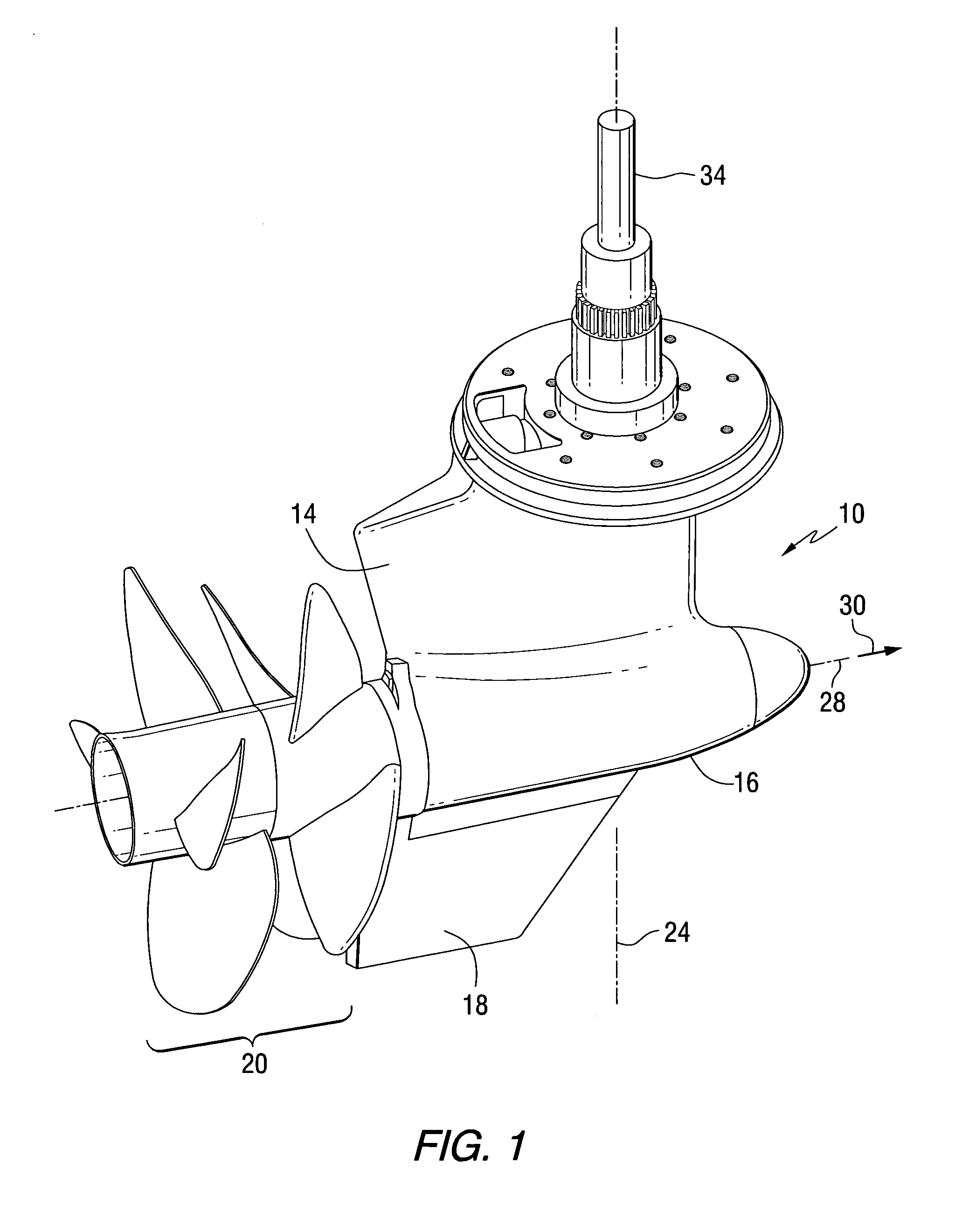
[0035]FIG. 1 is an isometric representation of a marine propulsion device 10. It is configured to extend downwardly through a hull and into the water below a marine vessel. The driveshaft housing 14, gear case 16, skeg 18, and the propellers 20 are supported below the wetted hull of a marine vessel. The marine propulsion device 10 is configured to be rotatable about a generally vertical steering axis 24. The propellers 20 are attached to a propeller shaft (not shown in FIG. 1) which is supported for rotation about a propeller shaft axis 28. The propellers 20 generate a thrust in a thrust direction 30 as represented by the arrow in FIG. 1.

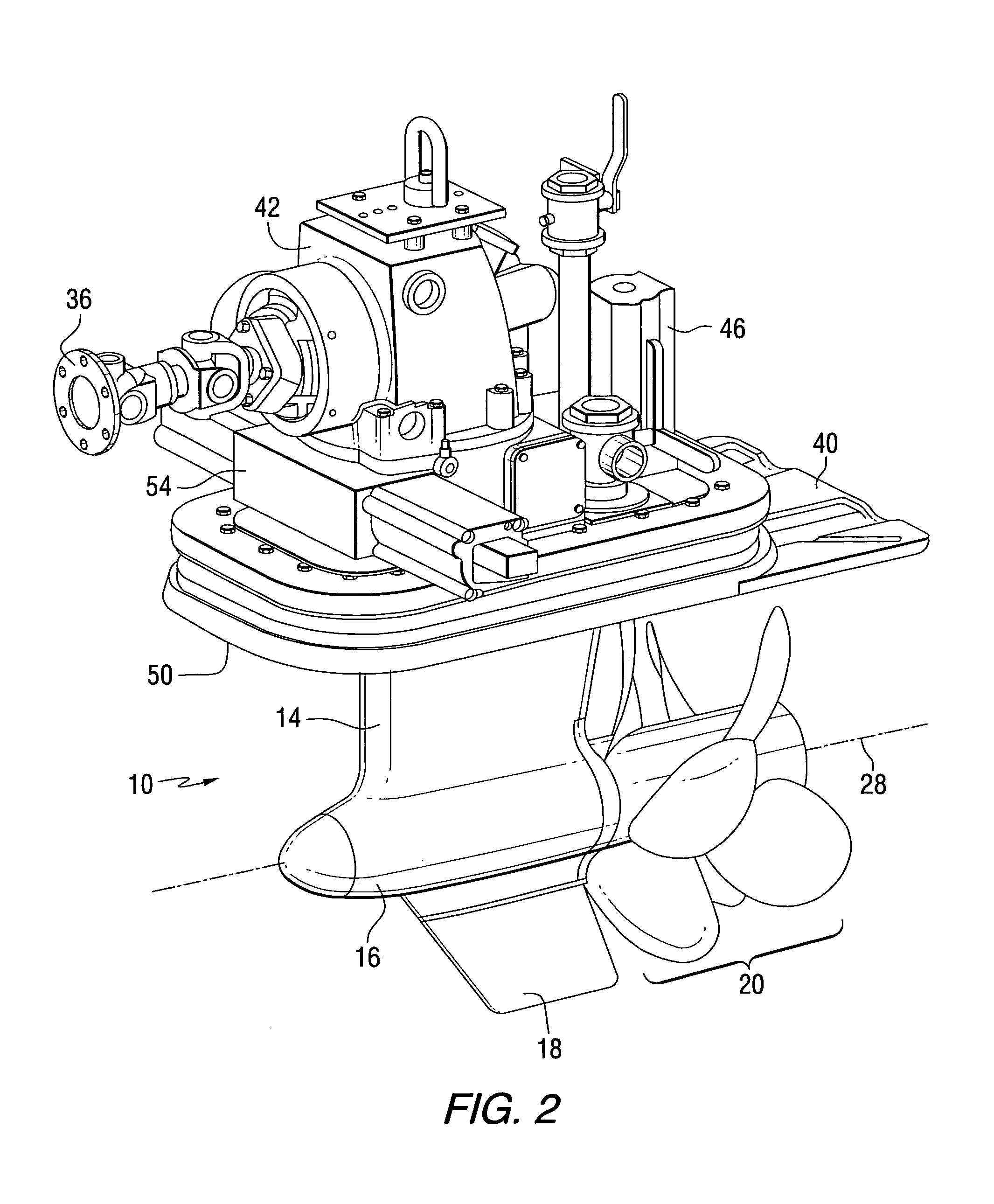
[0036]FIG. 2 shows the marine propulsion device 10 in combination with other components that are used to provide torque for the driveshaft 34, shown in FIG. 1, and the necessary force to affectuate stee...


PUM


Abstract

A method for controlling the movement of a marine vessel comprises steps that rotate two marine propulsion devices about their respective axes in order to increase the hydrodynamic resistance of the marine propulsion devices as they move through the water with the marine vessel. This increased resistance exerts a braking thrust on the marine vessel. Various techniques and procedures can be used to determine the absolute magnitudes of the angular magnitudes by which the marine propulsion devices are rotated.

Description

BACKGROUND OF THE INVENTION[0001]1. Field of the Invention[0002]The present invention is generally related to a marine vessel having two marine propulsion devices and, more particularly, to a method for slowing the forward movement of the marine vessel by appropriately changing the physical positions of the marine propulsion devices relative to the hull of the marine vessel.[0003]2. Description of the Related Art[0004]Many different types of marine propulsion systems are known to those skilled in the art. These include outboard motors, sterndrive devices, and systems in which one or more marine drives extend downwardly through the hull of the marine vessel.[0005]U.S. Pat. No. 5,735,718, which issued to Ekwall on Apr. 7, 1998, describes a drive unit for a boat having an engine with a flywheel surrounded by a flywheel casing, a propeller drive housing connected to, but electrically insulated from, the flywheel casing, and an input shaft for the propeller drive housing which is driven ...

Claims


Application Information

Patent Timeline
IPC IPC(8): B63H25/44
CPCB63H25/42B63H25/48B63H25/50
Inventor EHLERS, JEFFERY C.DAVIS, RICHARD A.
Owner BRUNSWICK CORPORATION
Why Eureka
Try Eureka