System and method for dynamic energy recovery in marine propulsion

a technology of dynamic energy recovery and marine propulsion, applied in marine propulsion, vessel auxillary drives, vessel construction, etc., can solve the problems of inability to change the direction of the propeller and/or thruster, e.g., to maintain the desired position of the vessel, and the bandwidth requirements for accurate position control may be too low relative to the bandwidth requirements

Active Publication Date: 2010-01-14
GE GLOBAL SOURCING LLC
View PDF8 Cites 27 Cited by
  • Summary
  • Abstract
  • Description
  • Claims
  • Application Information

AI Technical Summary

Problems solved by technology

In particular, DP may be used in oil and gas exploration, where vessels may be extended farther offshore from land in water depth sufficiently great that it is impractical to use anchor mooring systems.
However, the ability of the propeller and/or thrusters to maintain the desired position of the vessel may be limited by various factors.
For example, the ability to change direction of a propeller, e.g., to chan

Method used


Image

  • System and method for dynamic energy recovery in marine propulsion
  • System and method for dynamic energy recovery in marine propulsion
  • System and method for dynamic energy recovery in marine propulsion

Examples


Embodiment Construction

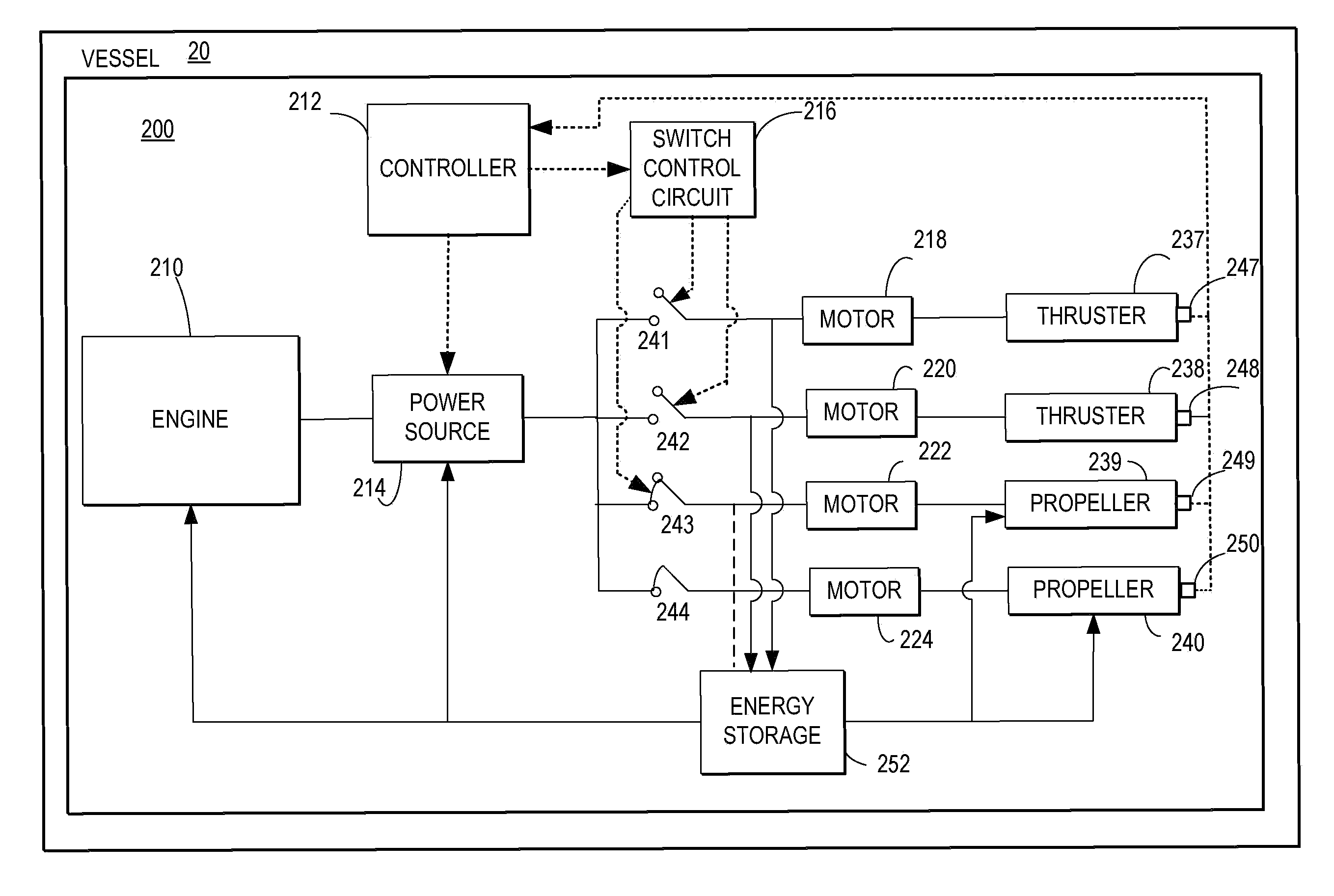
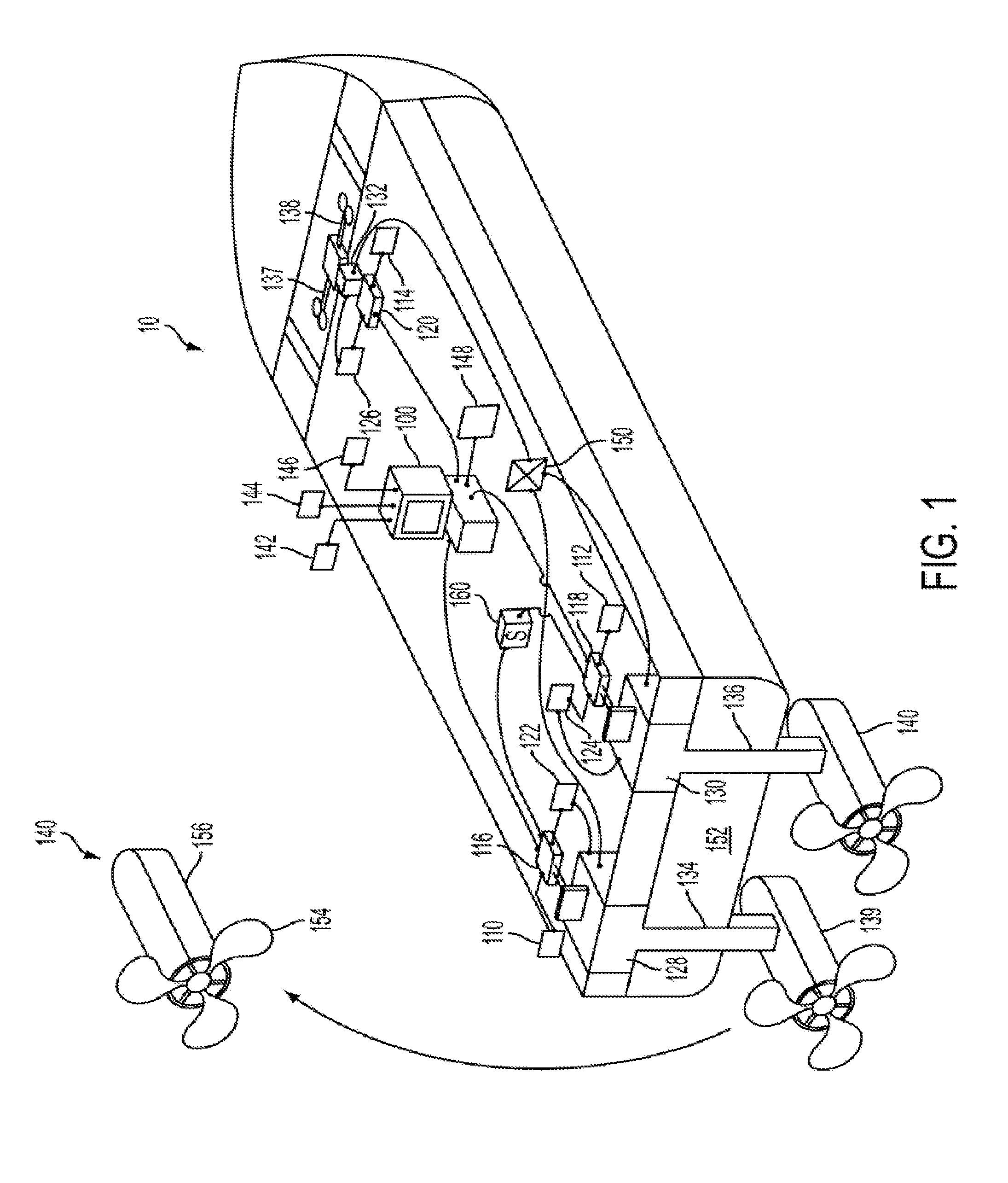
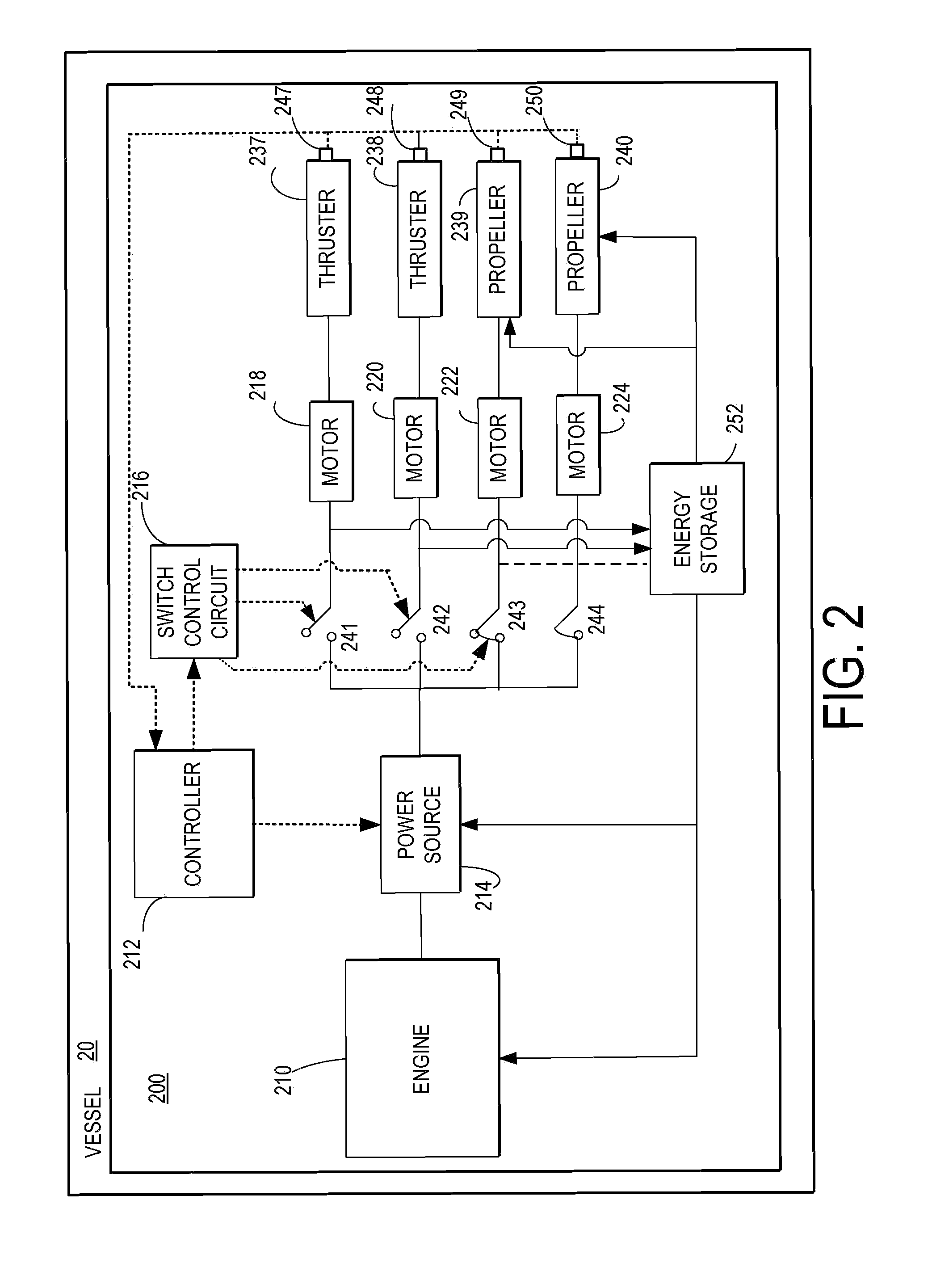
[0016]A waterborne vessel is described including a propulsion system and associated control system capable of accurately maintaining the vessel's position, referred to as a dynamic positioning. The position control utilizes one or more water flow actuators to generate stabilizing and position controlling forces and thereby counteracts wind, waves, and / or currents, for example. Further, the position control further varies an operating mode of the different water flow actuators so that at any condition, any of the water flow actuators may generate positive driving force / thrust, no force / thrust (idle), or negative braking force / thrust to maintain the vessel's position at a desired location. In some examples, braking energy may be harnessed via the propulsion system and used to drive other water flow actuators and / or charge an energy storage device for future energy requirements by other components or water flow actuators of the vessel. The following description, including the drawings,...


PUM


Abstract

A method for controlling operation of a propulsion system of a waterborne vessel, comprising adjusting recovery of energy generated from the propulsion system to maintain position of the waterborne vessel in response to at least an indication of vessel position.

Description

FIELD[0001]The present application relates to a propulsion system with dynamic positioning for marine applications.BACKGROUND[0002]Dynamic positioning (DP) is a computer control system to maintain a position of a vessel against environmental forces of current, wind and / or waves. The control system maintains position using propellers and / or thrusters on-board the vessel. A combination of position reference sensors and environmental sensors give position feedback for control of the position. In particular, DP may be used in oil and gas exploration, where vessels may be extended farther offshore from land in water depth sufficiently great that it is impractical to use anchor mooring systems.[0003]However, the ability of the propeller and / or thrusters to maintain the desired position of the vessel may be limited by various factors. For example, the ability to change direction of a propeller, e.g., to change the thrusting force generated, may be too slow relative to the bandwidth require...

Claims


Application Information

Patent Timeline
IPC IPC(8): B63H21/21
CPCB63B35/66B63H25/42B63H25/46Y02T70/74B63J3/04B63J2099/008B63H25/50Y02T70/10B63B79/15Y02T70/00
Inventor DAUM, WOLFGANGSTOTT, KYLEKUMAR, AJITH KUTTANNAIRPRASAD, REKHAMONG, TABMANISON, JOHN
Owner GE GLOBAL SOURCING LLC
Why Eureka
Try Eureka