Dual rate torque transmitting device for a marine propeller

a transmission device and propeller technology, applied in the field of marine propellers, can solve problems such as the condition of “propeller rattle”

Active Publication Date: 2006-08-08
BRUNSWICK CORPORATION
View PDF10 Cites 26 Cited by
  • Summary
  • Abstract
  • Description
  • Claims
  • Application Information

AI Technical Summary

Problems solved by technology

During transmission of low magnitudes of torque, rapid accelerations and decelerations of the propeller shaft, relative to the propeller hub, can result in a condition referred to as “propeller rattle”.

Method used


Image

  • Dual rate torque transmitting device for a marine propeller
  • Dual rate torque transmitting device for a marine propeller
  • Dual rate torque transmitting device for a marine propeller

Examples


Embodiment Construction

[0028]Throughout the description of the preferred embodiment of the present invention, like components will be identified by like reference numerals.

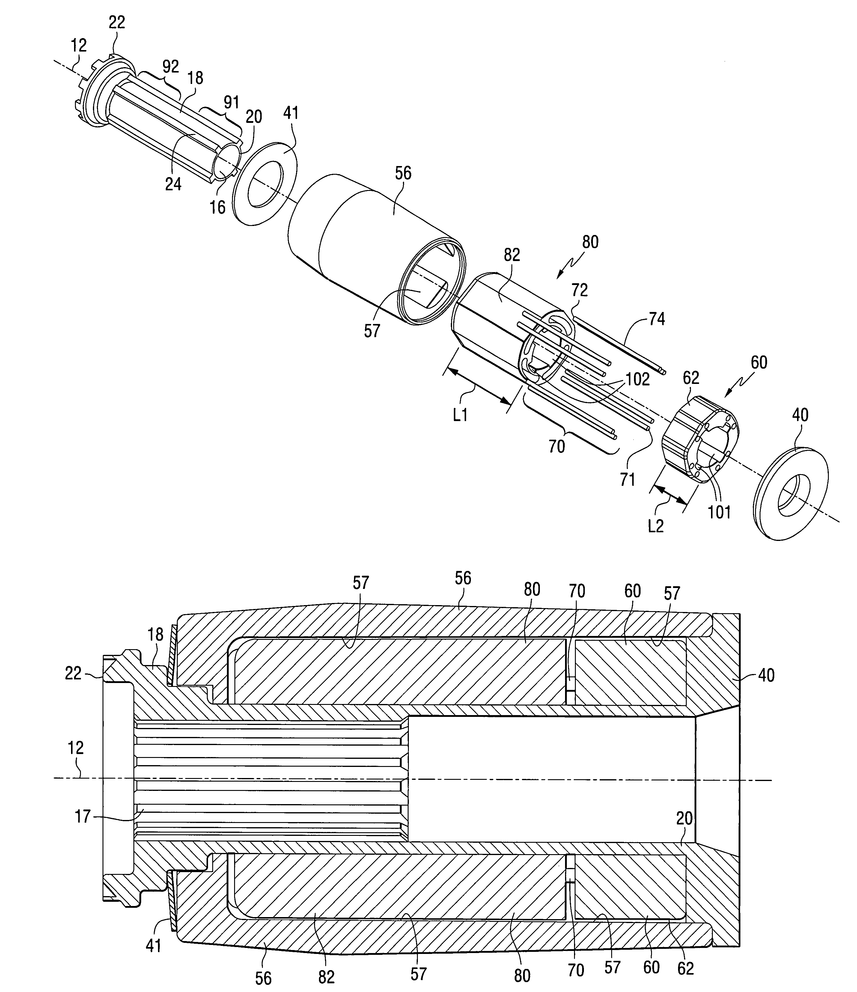
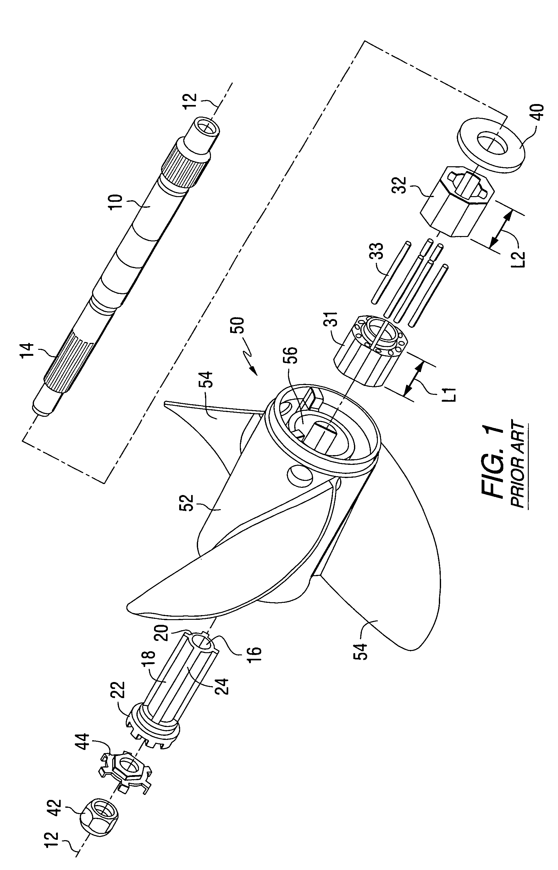
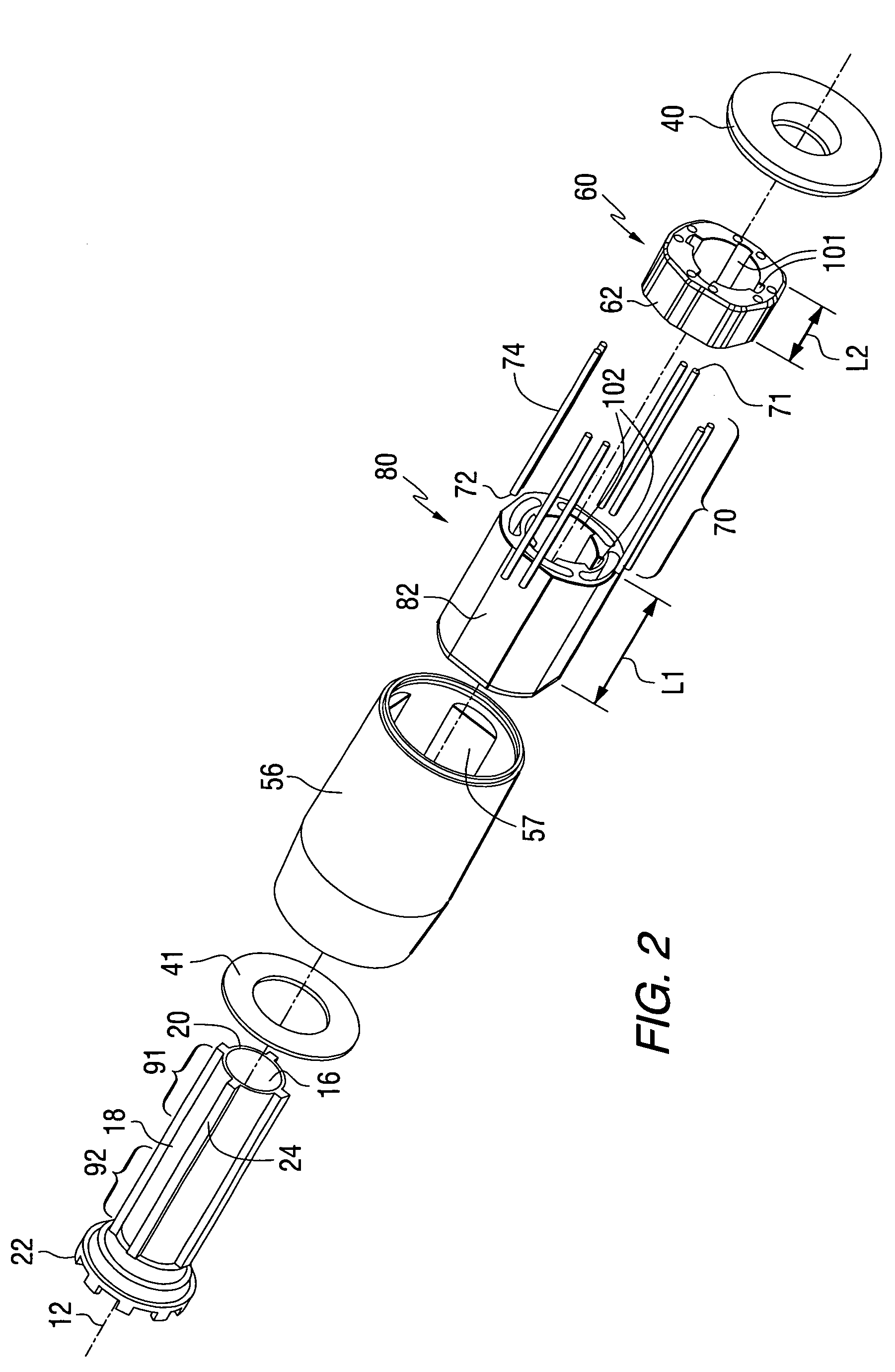
[0029]Figure one is an isometric exploded view of a torque transmitting device such as the one described in detail in U.S. Pat. No. 6,478,543. Although the preferred embodiment of the present invention transfers torque in a significantly different way than the system shown in FIG. 1 and described in U.S. Pat. No. 6,478,543, some of the individual components used in that known torque transfer system are generally similar to those used in a preferred embodiment of the present invention. Therefore, it is helpful to understand the structure and operation of the torque transmitting system shown in FIG. 1 in order to more fully appreciate the differences and advantages that are provided by a preferred embodiment of the present invention.

[0030]In FIG. 1, a propulsor shaft 10 is supported for rotation about an axis 12. The propulsor shaft 10 is...


PUM


Abstract

A torque transfer mechanism for a marine propulsion system provides a connector mechanism, a first torque transfer mechanism, and a second torque transfer mechanism. A plurality of rods can provide the first torque transfer mechanism and a polymer component is shaped to provide the second torque transfer mechanism. All torque below a preselected magnitude is transferred through the first torque transfer mechanism and, for magnitudes of torque above the threshold, torque is transferred by both the first and second torque transfer mechanisms. The connector mechanism has an outer surface that is not used to transfer torque between it and an inner hub of a propulsor.

Description

BACKGROUND OF THE INVENTION[0001]1. Field of the Invention[0002]The present invention is generally related to a marine propeller and, more particularly, to a dual rate torque transmitting device which reduces noise at low torque magnitudes while maintaining the capacity to transmit higher torque magnitudes.[0003]2. Description of the Prior Art[0004]Those skilled in the art of marine propellers are familiar with various devices which have been provided to attach a propeller to a propeller shaft in a way which provides a certain degree of resilience in the torque transmitting connection.[0005]U.S. Pat. No. 4,566,855, which issued to Costabile et al. on Jan. 28, 1986, describes a shock absorbing clutch assembly for a marine propeller. The propeller hub has an axial hole therein having a wavy, non-cylindrical surface consisting of a plurality of alternating peaks and valleys. A closely fitting resilient insert slips into the axial hub hole of the propeller hub and has an outer surface w...

Claims


Application Information

Patent Timeline
Patent Type & Authority Patents(United States)
IPC IPC(8): B63H23/34
CPCB63H23/34B63H1/20B63H2023/346B63H2023/344B63H2023/342B63H1/15
Inventor SHETH, MITESH B.MIHELICH, MICHAEL P.TUCHSCHERER, JOHN A.KOEPSEL, ROGER E.SCHLAGENHAFT, DANIEL J.
Owner BRUNSWICK CORPORATION
Why Eureka
Try Eureka