
Automatic bone mill

a bone mill and automatic technology, applied in the field of surgical instruments and their use, can solve the problems of introducing time and expense, affecting the quality of bone grinding,

Inactive Publication Date: 2006-11-07
MEDTRONIC PS MEDICAL
View PDF3 Cites 31 Cited by
  • Summary
  • Abstract
  • Description
  • Claims
  • Application Information

AI Technical Summary

Benefits of technology

The present invention provides a system and method for using a bone mill in a sterile environment. The system includes a sterile casing for the bone mill, a particle reducer, a motor, and a detachable coupling for connecting the particle reducer to the motor. The system can be used with a hand-held powered bone mill or an automatic bone mill. The detachable coupling allows for easy sterilization and replacement of the bone mill. The invention provides a more efficient and sterile way to break bone and other materials in a surgical environment.

Problems solved by technology

The step of grinding the portion of bone using a hand-powered rasp is a relatively long and strenuous operation, with mixed results depending on the bone, the rasp, and the operator's ability.
This process also introduces an element of time and expense that must be accounted for in the surgical procedure.
Furthermore, rasps in general have certain deficiencies.
Rasps are inherently wasteful, it being difficult to remove all of the bone particles there from.
Also, there is no way to mix various additives to the bone particles, such as an additive that promotes bone growth, during the milling process.

Method used


Image

  • Automatic bone mill
  • Automatic bone mill
  • Automatic bone mill

Examples


Embodiment Construction

[0051]The following description of the preferred embodiments is merely exemplary in nature and is in no way intended to limit the invention, its application, or uses. In addition, the following description may repeat reference numerals and / or letters in the various embodiments. This repetition is for the purpose of simplicity and clarity and does not in itself dictate a relationship between the various embodiments and / or configurations discussed.

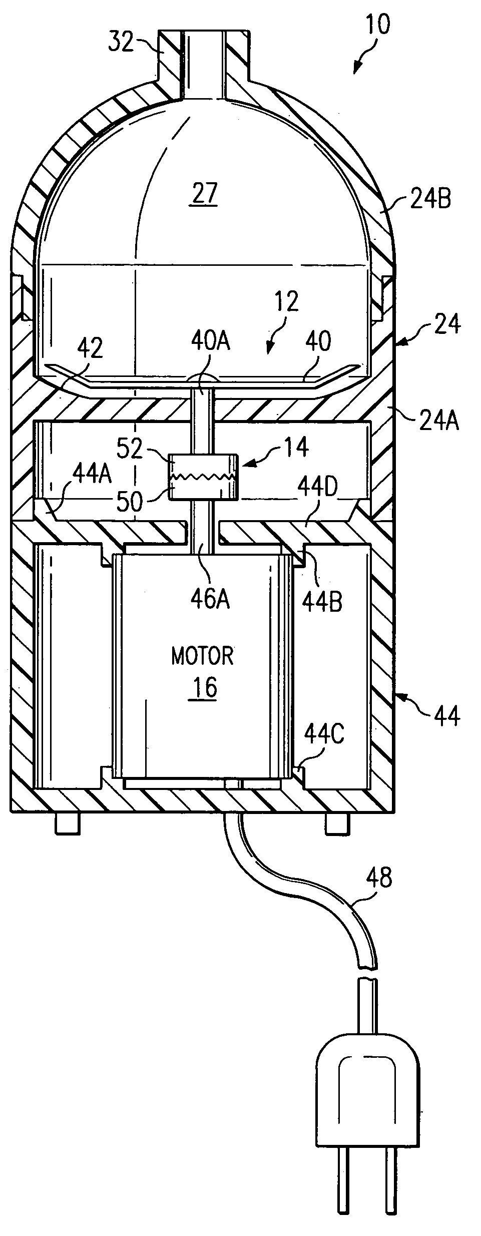
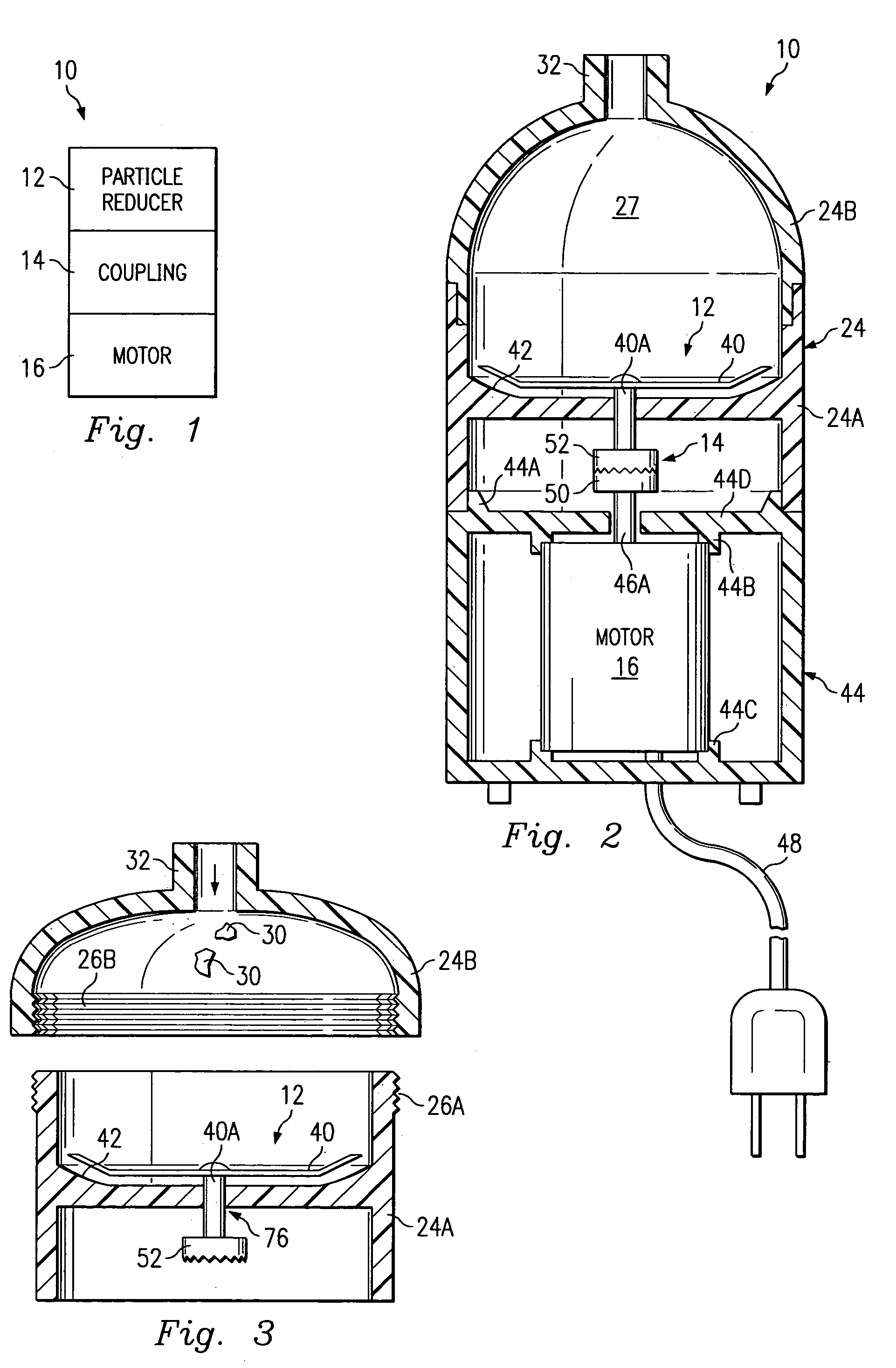
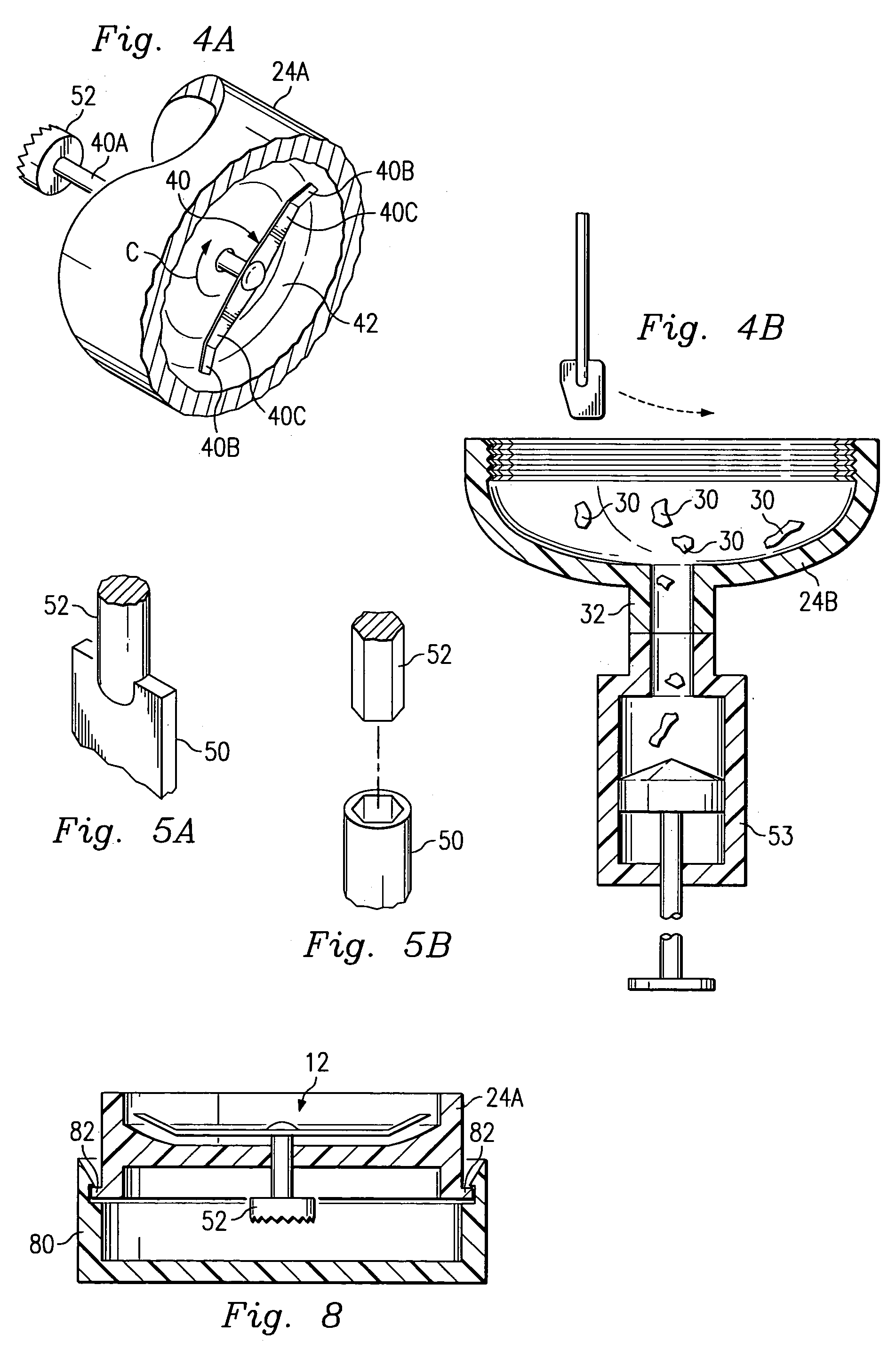
[0052]Referring to FIG. 1, the reference numeral 10 designates, in general, an automatic bone mill for implementing features of the present invention. The bone mill 10 includes a particle reducer 12, a coupling 14, and a motor 16. The particle reducer 12 is capable of reducing one or more pieces of bone and / or other material into smaller particles. The motor 16 is used for moving the particle reducer in an automatic fashion. The coupling 14 is for connecting the motor 16 to the particle reducer 12, and in some embodiments, may allow for rela...


PUM


Abstract

A bone mill for use in a surgical or otherwise sterile environment includes a particle reducer such as a pulverizing blade, a motor such as an electrical motor, and a coupling such as a rotary shaft for connecting the particle reducer to the motor.

Description

CROSS-REFERENCE TO RELATED APPLICATIONS[0001]This is a continuation-in-part of patent application Ser. No. 10 / 184,444, filed on Jun. 28, 2002, Automatic Bone Mill, now U.S. Pat. No. 6,824,087, assigned to same assignee as the present invention, which is incorporated by reference in its entirety.FIELD OF THE INVENTION[0002]The present invention generally relates to surgical instruments and their use. More particularly, the present invention relates to a bone mill for use in a surgical, medical, or other environment where ground bone particles are needed.[0003]Ground bone particles can be used in various medical and surgical procedures. For example, finely ground bone particles can be used for spinal fusions, to repair defects caused by trauma, transplant surgery, or tissue banking. In this example, a surgeon may remove a portion of bone from a patient, grind the portion into fairly homogenous particles using a hand-powered rasp, and use the bone particles to patch and repair another ...

Claims


Application Information

Patent Timeline
Patent Type & Authority Patents(United States)
IPC IPC(8): B02C19/00A61F2/46B02C18/12
CPCA61F2/4644B02C18/12B02C19/0056A61F2002/4645
Inventor MCPHERSON, CAMERONCHOWDIAH, SREENIVASSINGER, SCOTT A.ELLINS, ROBFOLEY, KEVIN
Owner MEDTRONIC PS MEDICAL
Learn More