Retaining wedge for concrete forms

a technology for concrete forms and wedges, applied in the direction of forming/stuttering elements, building parts, fastening means, etc., can solve the problems of raising safety issues, exacerbate the problem, and conventional wedges can also be difficult to insert into the retaining slots, so as to facilitate the quick starting of the wedge, raise the safety issue, and increase the risk of losing the wedge

Inactive Publication Date: 2006-11-07
WESTERN FORMS
View PDF11 Cites 1 Cited by
  • Summary
  • Abstract
  • Description
  • Claims
  • Application Information

AI Technical Summary

Benefits of technology

[0004]Conventional wedges can also sometimes be difficult to insert into the retaining slots, particularly where the slots are small and the wedges must be used in tight spaces. Furthermore, conventional wedges sometimes spring into the air when they are driven out of their slots during stripping of the forms from the cured concrete, raising safety issues and increasing the risk of lost wedges.
[0005]The present invention provides a wedge that overcomes many of the shortcomings of the prior art. In a preferred form, the generally trapezoidal or triangular body of the wedge includes one or more depressions along at least one of its side edges that serves as a type of holding detent when the wedge is driven into place. Notwithstanding its secure holding action, the detent can be forcibly overcome during intentional removal of the wedge. Preferably, the wedge is provided with a more slender tip than conventional wedges so as to facilitate quick starting of the wedge when inserted into a slot and driven home. However, the remaining body of the wedge tapers outwardly at a fairly rapid rate so the wedge can be used with larger exposed slots, as well as narrow ones. This permits one size wedge to be used in a variety of different slot size situations, and eliminates the need to carry a variety of wedge sizes.

Problems solved by technology

However, this requires the installer to keep a large inventory of different sizes on hand at all times. Moreover, selecting just the right size wedge for a particular situation from a large inventory of different sizes can be a nuisance.
Typically, the wedges are provided in both flat and slightly curved models, which further exacerbates the problem.
Conventional wedges can also sometimes be difficult to insert into the retaining slots, particularly where the slots are small and the wedges must be used in tight spaces.
Furthermore, conventional wedges sometimes spring into the air when they are driven out of their slots during stripping of the forms from the cured concrete, raising safety issues and increasing the risk of lost wedges.

Method used


Image

  • Retaining wedge for concrete forms
  • Retaining wedge for concrete forms
  • Retaining wedge for concrete forms

Examples


Embodiment Construction

[0013]The present invention is susceptible of embodiment in many different forms. While the drawings illustrate and the specification describes certain preferred embodiments of the invention, it is to be understood that such disclosure is by way of example only. There is no intent to limit the principles of the present invention to the particular disclosed embodiments.

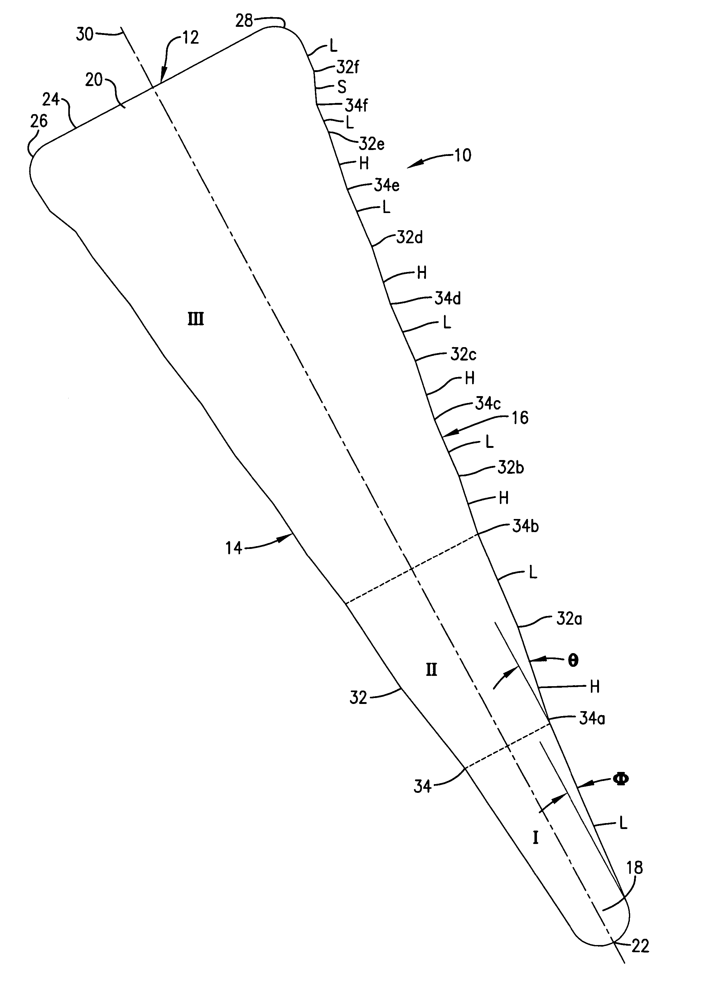
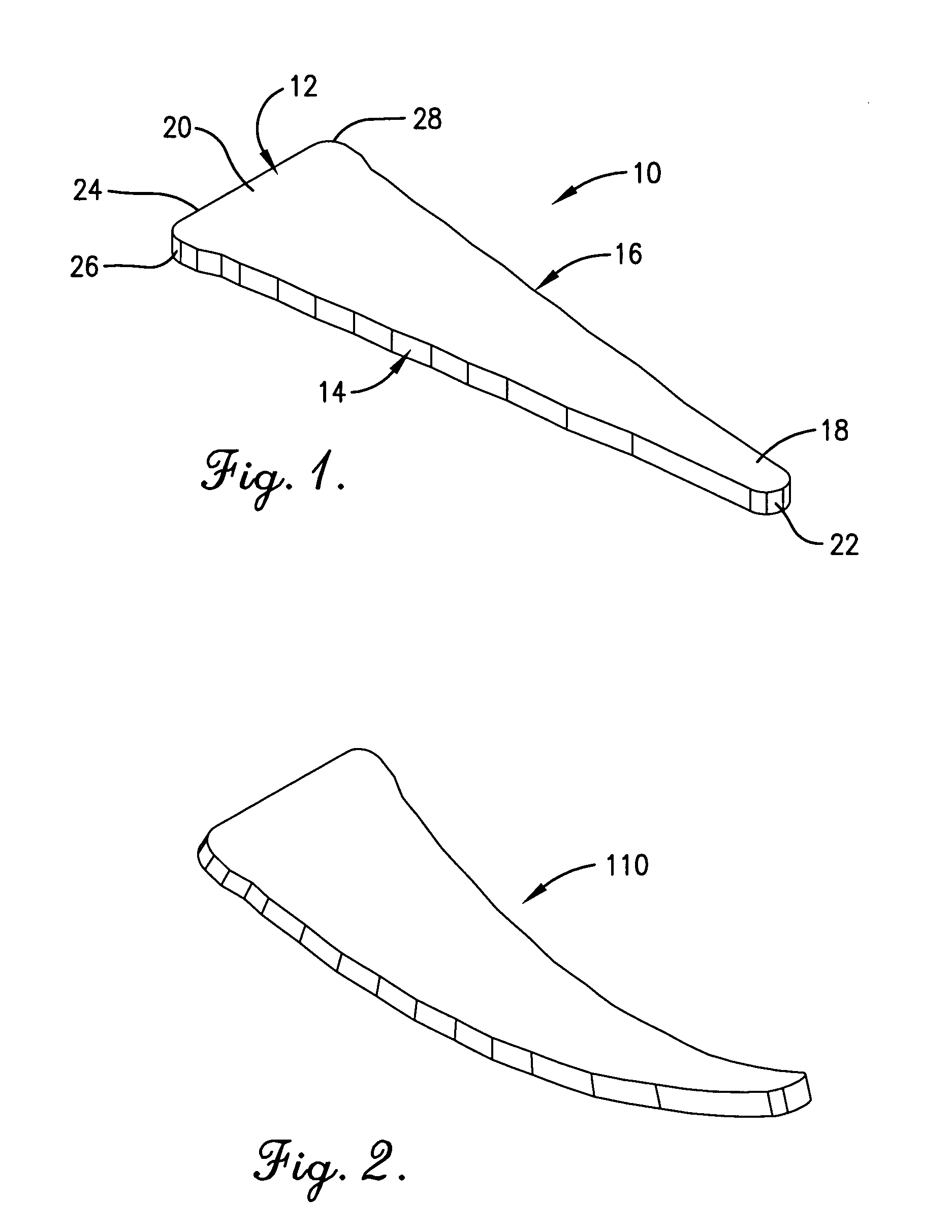
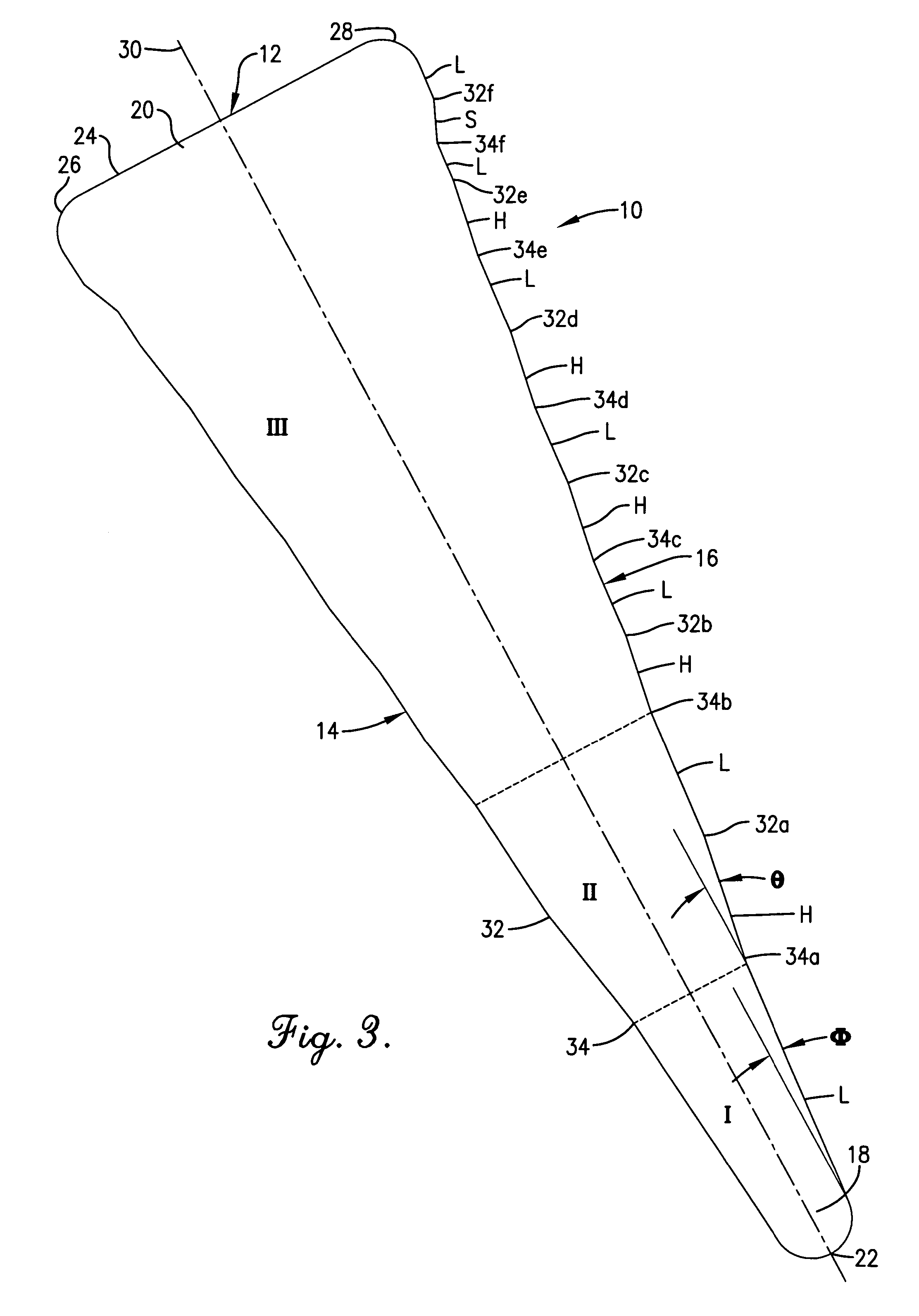
[0014]With initial reference to FIG. 1, the wedge 10 therein disclosed comprises a generally triangular or trapezoidal body 12 that is preferably constructed from flat, sheet steel material so as to present a constant thickness throughout its entire length and width. Body 12 presents a pair of opposite side edges 14 and 16 that mutually diverge from a tip 18 at one end of body 12 toward a head 20 at the opposite end thereof. Tip 18 has a rounded point 22, while head 20 has a straight, flat end 24 that is perpendicular to the longitudinal axis of body 12. Head 20 is enlarged across its width relative to the rest of the ...


PUM


Abstract

A retaining wedge for concrete forms has a tapered body of generally trapezoidal or triangular configuration. Oppositely diverging side edges of the body are provided with alternating peaks and valleys so as to present a number of detent-like depressions that encourage a firm and secure gripping action when the wedge is driven into the retaining slot of a locking pin that interconnects a pair of adjacent form panels. The peaks and valleys along each edge are presented by alternating convex and concave intersections between successive edge portions that slope outwardly at different angles from one another. Although certain portions of the edge slope outwardly at a higher angle than others, no edge portions slope inwardly toward the longitudinal axis of the wedge body. Consequently, the wedge is constantly tapering over its full length from one end to the other. A long, slender tip of the wedge facilitates insertion and fast starts.

Description

TECHNICAL FIELD[0001]This invention relates to the field of forming panels used in the creation of concrete walls and the like. More particularly, it relates to improvements in the hardware used to releasably fasten together adjacent panels of the form.BACKGROUND AND SUMMARY[0002]It is well known in the art to fasten together upstanding, adjacent forming panels using a locking pin that passes through aligned openings in the two panels and a retaining wedge that fits into a cross slot in the pin. The wedge bears against the end of the pin slot on the one hand and adjacent surfaces of the panel on the other and is usually driven tightly into place using a hammer or the like. Typically, the holes that receive the locking pins are formed in side rails on the panels that may be a variety of different thicknesses. Consequently, the pin slot may project through the holes to a greater or lesser extent, depending upon any given situation, which causes the dimensions of the slot that is expos...

Claims


Application Information

Patent Timeline
Patent Type & Authority Patents(United States)
IPC IPC(8): F16B19/00
CPCF16B21/12
Inventor BREWKA, ROMAN
Owner WESTERN FORMS
Why Eureka
Try Eureka