
Electrical connector and airbag apparatus having an electrical connector

Inactive Publication Date: 2006-11-07
LEAR CORP
View PDF22 Cites 30 Cited by
  • Summary
  • Abstract
  • Description
  • Claims
  • Application Information

AI Technical Summary

Benefits of technology

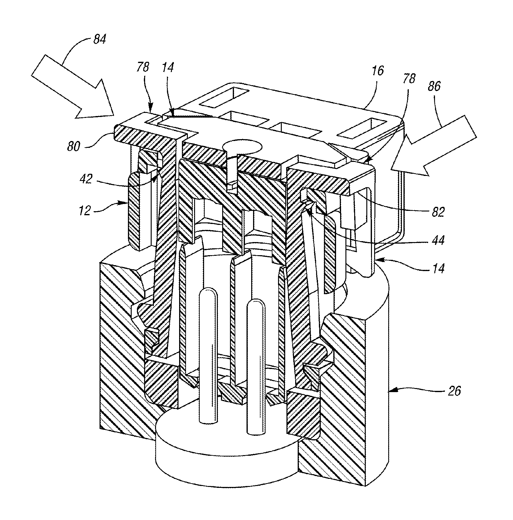
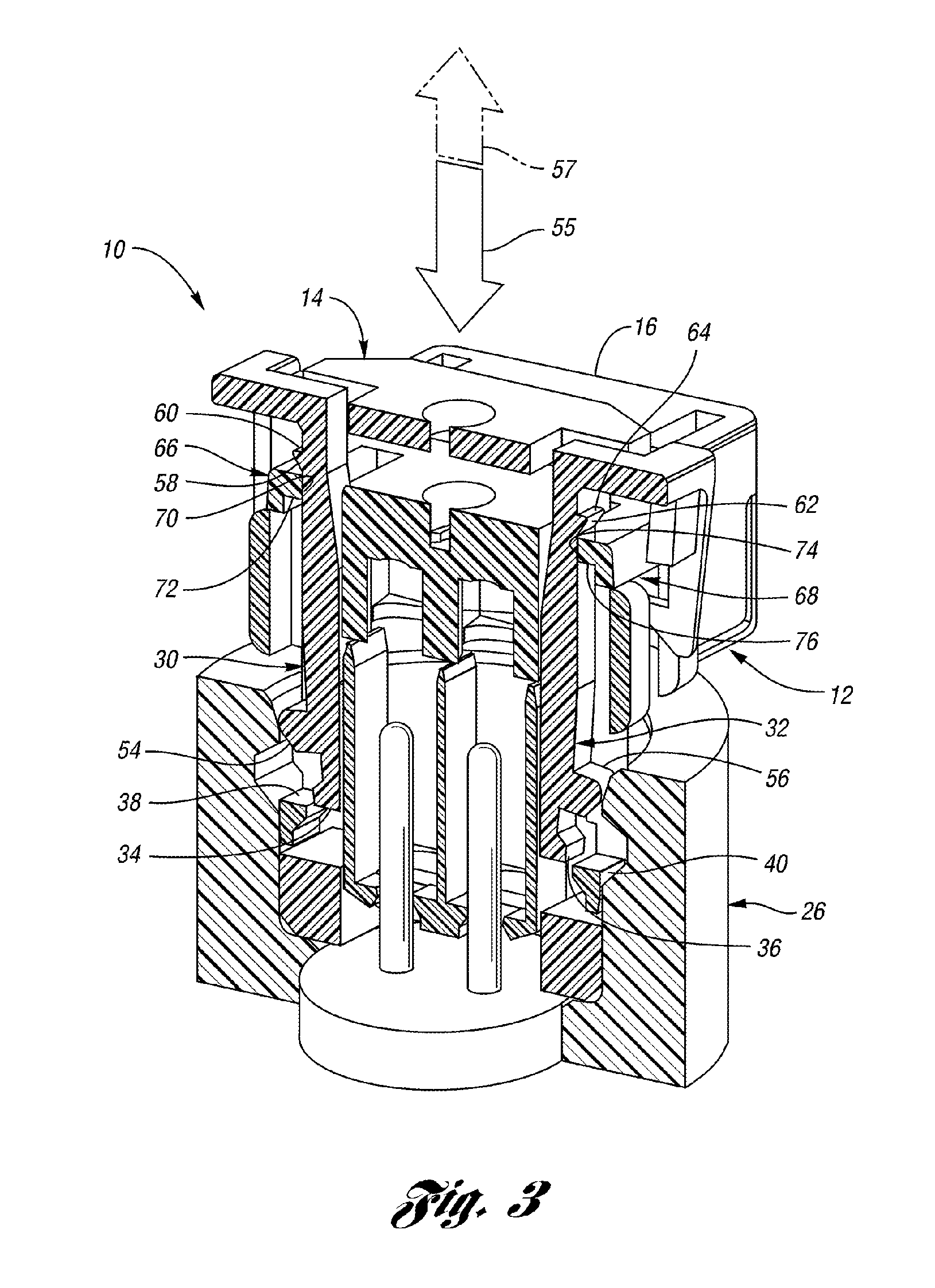
[0014]The invention also provides a vehicle airbag apparatus which includes an initiator having an initiator connector housing attached thereto. A first connector housing is configured to cooperate with the initiator connector housing in a mated position for making an electrical connection with the initiator. A retainer is movable between first and second retainer positions. The first retainer position facilitates movement of the first connector housing into and out of the mated position. The second retainer position inhibits movement of the first connector housing out of the mated position. The retainer includes a locking feature configured to engage the first connector housing to inhibit movement of the retainer out of the second retainer position. The locking feature is at least partially disengageable from the first connector housing to facilitate movement of the retainer out of the second retainer position.

Problems solved by technology

One limitation of the CPA described in Shuey et al. is that it can be dislodged from its fully seated position merely by applying an extraction force to the CPA.
Disengagement of a CPA while the connector is in service may be particularly problematic in certain applications where the electrical connector is subjected to relatively large forces.
For example, in the case of a vehicle airbag, the electrical connection at the airbag initiator may encounter large forces when the airbag deploys.
This is because airbag initiators may be configured with a service safety feature which does not allow the initiator to function unless the electrical connector is fully engaged and the CPA is fully seated.
Thus, even a small amount of movement of the CPA out of its fully seated position will allow the short circuit to close, thereby disabling the initiator.

Method used


Image

  • Electrical connector and airbag apparatus having an electrical connector
  • Electrical connector and airbag apparatus having an electrical connector
  • Electrical connector and airbag apparatus having an electrical connector

Examples


Embodiment Construction

)

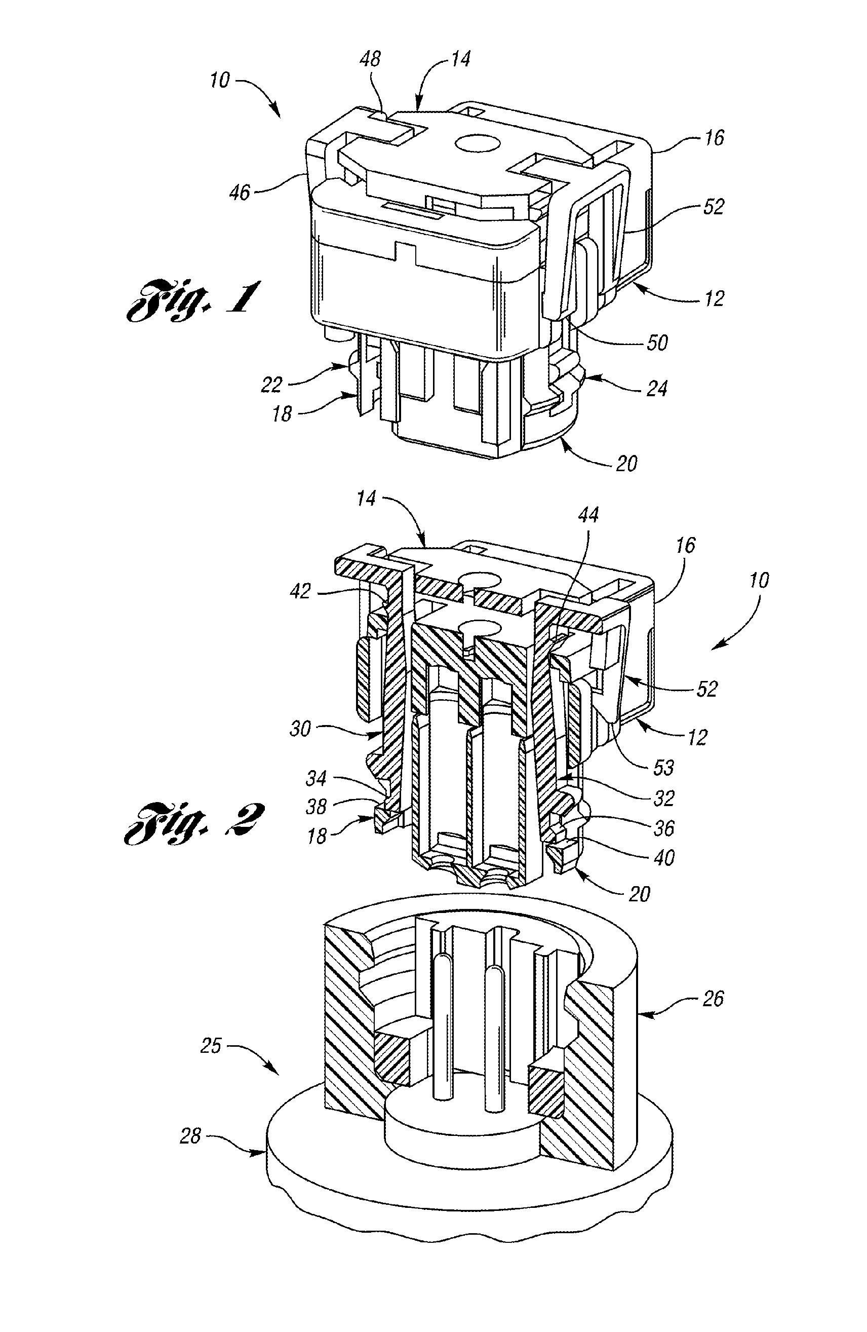
[0020]FIG. 1 shows an electrical connector 10 in accordance with one embodiment of the present invention. The connector 10 includes a first connector housing 12 and a retainer, or connector position assurance device 14, which, as shown in FIG. 1, is in a first retainer position. The first connector housing 12 includes a cover 16 which can be used to cover electrical connections (not shown) inside the first connector housing 12. The first connector housing 12 also includes first and second locking legs 18, 20, which, as explained more fully below, are configured to mate with a second connector housing to facilitate making of an electrical connection. In particular, each of the locking legs 18, 20 includes locking bumps 22, 24 which are received by a slot inside the second connector housing.

[0021]FIG. 2 shows a sectional view of the electrical connector 10, and also shows a vehicle airbag apparatus 25, including a sectional view of a second connector housing, or initiator connector h...


PUM


Abstract

An electrical connector includes a first connector housing which is configured to cooperate with a second connector housing in a mated position to facilitate making an electrical connection. A connector position assurance device (CPA) is configured to cooperate with the first connector housing in a first position to allow engagement and disengagement of the first and second connector housings. The CPA has a second position which inhibits disengagement of the first and second connector housings from the mated position. The CPA also includes a locking feature configured to engage the first connector housing to inhibit unseating of the CPA. The CPA also includes a release mechanism which is operable from outside the first connector housing, and allows the locking feature to be disengaged from the first connector housing to facilitate unseating of the CPA.

Description

BACKGROUND OF THE INVENTION[0001]1. Field of the Invention[0002]The present invention relates to an electrical connector and a vehicle airbag apparatus having an electrical connector.[0003]2. Background Art[0004]Electrical connectors, and in particular, plug-type electrical connectors, can provide a fast and convenient way to connect and disconnect electrically operated devices. In the case of a plug-type connector, it may be necessary for the two portions of the plug—e.g., the male and female portions—to be fully seated to ensure an adequate electrical connection. One way to help ensure that two portions of an electrical connector are fully seated with each other, is through the use of a connector position assurance device (CPA).[0005]A CPA can be configured such that it cooperates with the electrical connector to provide a visual assurance that the connector is fully seated. For example, a CPA may have seated and unseated positions which are readily discernible by visual inspectio...

Claims


Application Information

Patent Timeline
IPC IPC(8): H01R13/62
CPCH01R13/6273H01R13/633H01R13/639H01R13/7032H01R13/6275H01R13/641
Inventor PAVLOVIC, SLOBADANMENZIES, DAVID
Owner LEAR CORP
Learn More