Modular conveying systems and methods

Active Publication Date: 2014-07-10
SOLUS INDAL INNOVATIONS
View PDF5 Cites 8 Cited by
  • Summary
  • Abstract
  • Description
  • Claims
  • Application Information

AI Technical Summary

Benefits of technology

[0025]In some implementations, the plurality of rolling elements are positioned the recesses of the module body (e.g., one rolling element per recess). In various implementations, the rolling elements can move (e.g., spin) relative to the module body. Accordi

Problems solved by technology

Over time, friction between the moving parts in the conveyor system can cause wear.
In some instances, indivi

Method used


Image

  • Modular conveying systems and methods
  • Modular conveying systems and methods
  • Modular conveying systems and methods

Examples


Example

[0064]A variety of modular conveyors and modular conveyor systems are described below to illustrate various examples that may be employed to achieve one or more desired improvements. These examples are only illustrative and not intended in any way to restrict the general inventions presented and the various aspects and features of these inventions. Furthermore, the phraseology and terminology used herein is for the purpose of description and should not be regarded as limiting. No features, structure, or step disclosed herein is essential or indispensible.

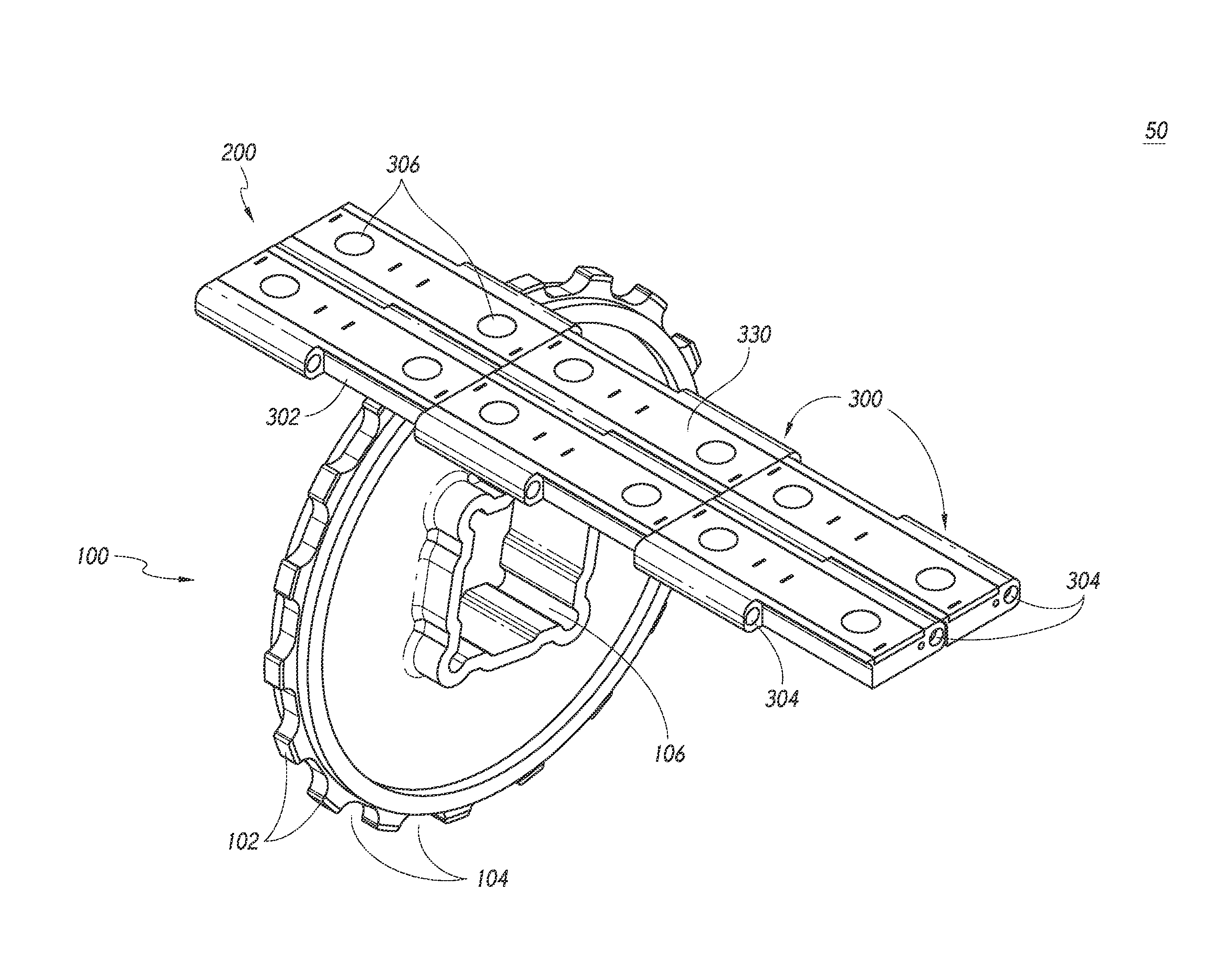
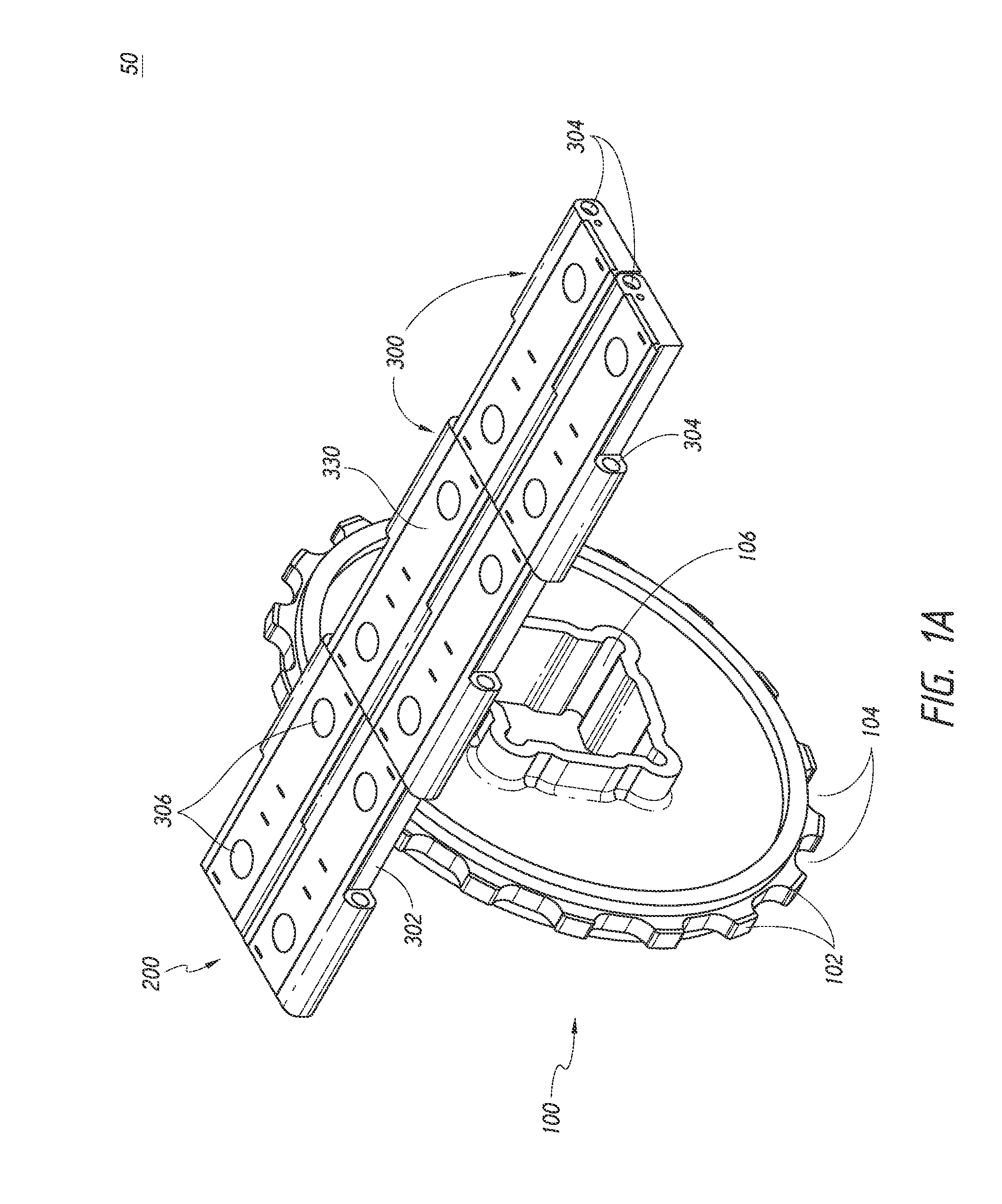
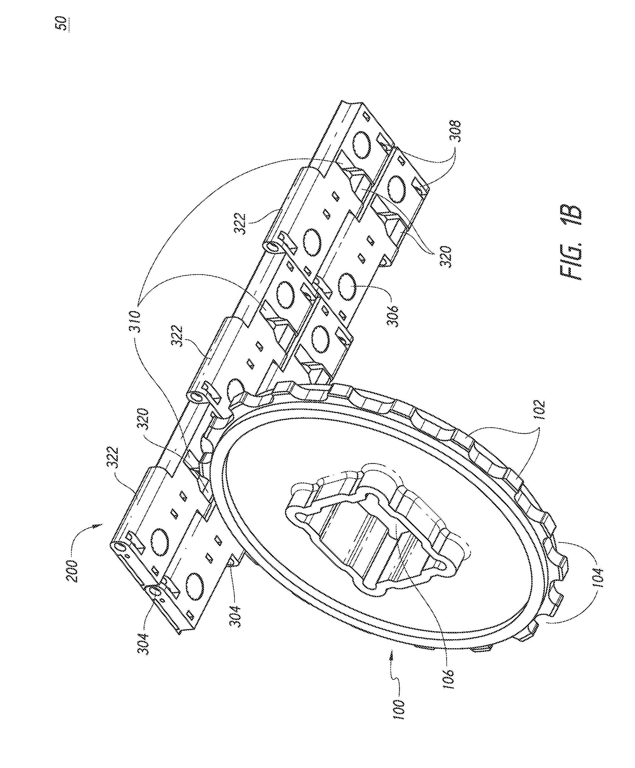
[0065]FIGS. 1A and 1B illustrate an embodiment of a portion of a modular conveyor system 50. The modular conveyor system 50 can include a modular conveyor 200 having a plurality of modules 300. In some embodiments, the modules 300 are connected to form an endless loop (e.g., a conveyor belt). In some embodiments, the modules 300 are configured to engage a sprocket 100, which can encourage movement of the modular conveyor 200 and thu...


PUM


Abstract

Various modular conveyors, conveying systems, conveyor modules, and methods are disclosed. In some embodiments, the conveyor comprises a module body and an upper member. The module body can be configured to receive one or more rolling elements. In some embodiments, the rolling elements protrude through openings in the module body and the upper member. In various embodiments, the rolling elements can be configured to engage a surface below the module body and/or an item on the conveyor, thereby facilitating multi-directional travel of the item.

Description

CROSS REFERENCE TO RELATED APPLICATIONS[0001]All applications for which a foreign or domestic priority claim is identified in the Application Data Sheet as filed with the present application are hereby incorporated by reference herein under 37 C.F.R. § 1.57.[0002]The present application claims the priority benefit under at least 35 U.S.C. § 119 of U.S. Patent Application No. 61 / 750,246, filed Jan. 8, 2013, the entirety of which is hereby incorporated by reference herein.BACKGROUND[0003]1. Field[0004]The disclosure relates generally to the field of conveyors and, in some embodiments, to modular conveyors and modular conveyor systems.[0005]2. Description of the Related Art[0006]Conveyors are commonly employed in various commercial and manufacturing applications to transport objects between different processing stations and locations. A conveyor typically includes a conveyor belt or chain that is arranged in an endless loop and driven to transport the objects on the belt or chain surfa...

Claims


Application Information

Patent Timeline
IPC IPC(8): B65G15/30
CPCB65G15/30B65G17/08B65G2207/12B65G17/24B65G17/40B65G39/20
Inventor PORTER, JIMPARRISH, KELLYIRELAND, LANCE
Owner SOLUS INDAL INNOVATIONS
Why Eureka
Try Eureka