Eureka AIR delivers breakthrough ideas for toughest innovation challenges, trusted by R&D personnel around the world.

Motorized chamber lid

Inactive Publication Date: 2008-05-13
APPLIED MATERIALS INC
View PDF28 Cites 9 Cited by
  • Summary
  • Abstract
  • Description
  • Claims
  • Application Information

AI Technical Summary

Benefits of technology

[0010]A semiconductor processing chamber having a motorized lid is provided. In one embodiment, the semiconductor processing chamber generally includes a chamber body having sidewalls and a bottom defining an interior volume. A lid assembly is coupled to the chamber body and is movable between a first position that encloses the interior volume and a second position. A hinge assembly thereto is coupled between the lid assembly and the chamber body. A motor is coupled to the hinge assembly to facilitate moving the lid assembly between the first position and the second position.
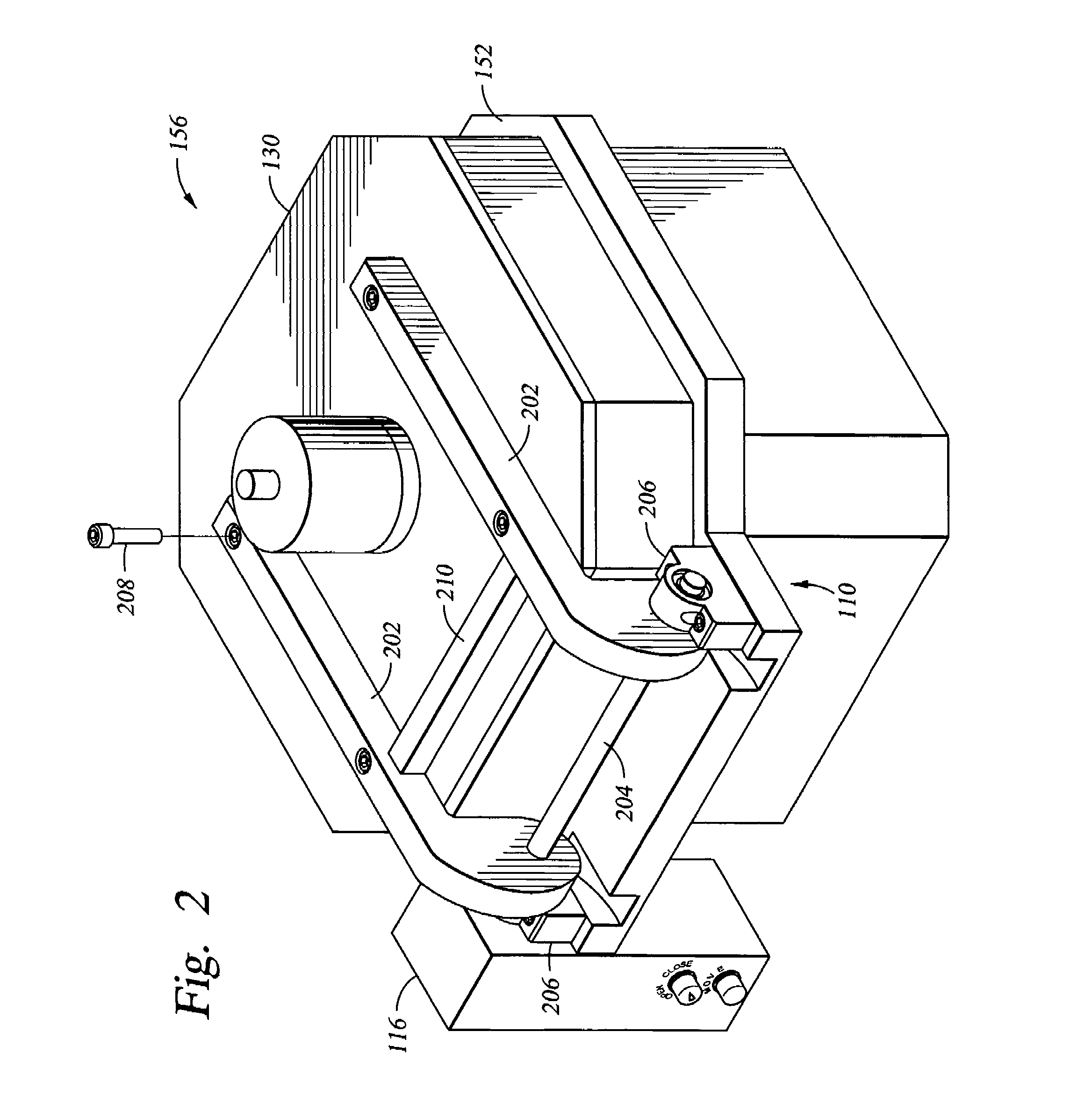
[0011]In another embodiment, the semiconductor processing chamber generally includes a chamber body having sidewalls and a bottom defining an interior volume. A lid is coupled to the chamber body and has a bottom movable between a first position that encloses the interior volume and a second position. A target is coupled to the bottom of the lid. One or more mounting brackets are coupled to the lid assembly and a shaft that is rotatably coupled to one or more bearing mounts. A motor is coupled to at least one of the shaft or mounting brackets and moves the lid assembly between the first position and the second position. In one alternative embodiment, the shaft is coplanar with an upper surface of the chamber body to reduce wear of a seal that is disposed between the lid and chamber body when closing the lid.

Problems solved by technology

The weight of these lid assemblies has led to the incorporation of spring, gas pots and counterbalances for facilitating the opening and closing of the lid assembly.
Although the systems have been successfully employed to assist in reducing the force required to open the lid assembly, each arrangement has some attribute that is generally not favorable for semiconductor processing.
For example, systems employing springs generally are not favored due to the possibility of particulate contamination.
As these springs are typically located at or near the lid assembly, these particles may fall into the processing chamber and cause subsequent contamination during wafer processing.
Moreover, as the center of gravity for the lid assembly and counterbalance often are not matched about the center of rotation of the lid assembly, the force required to open the lid assembly may vary as the lid assembly is rotated away from the chamber.
This makes opening the lid assembly difficult to control.

Method used


Image

  • Motorized chamber lid
  • Motorized chamber lid
  • Motorized chamber lid

Examples


Embodiment Construction

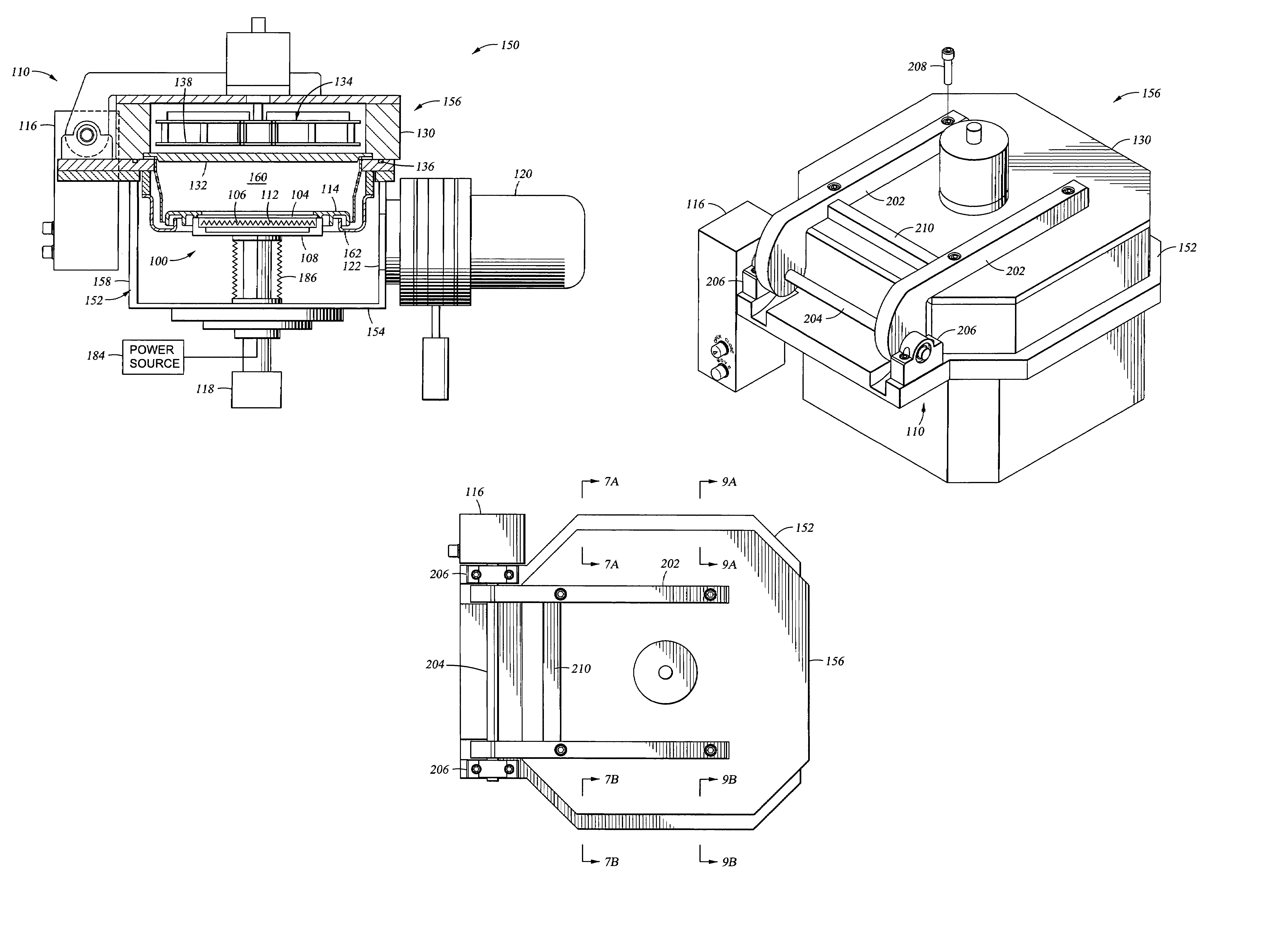
[0025]The invention generally provides a semiconductor processing chamber having a lid controllably opened and closed by a motor assembly. Although the invention is disclosed and illustrated in a physical vapor deposition (PVD) chamber, the disclosure is one of illustration, and accordingly, the invention finds utility in other semiconductor processing chambers including transfer chambers, load lock chambers, etch chambers and chemical vapor deposition chambers among others.

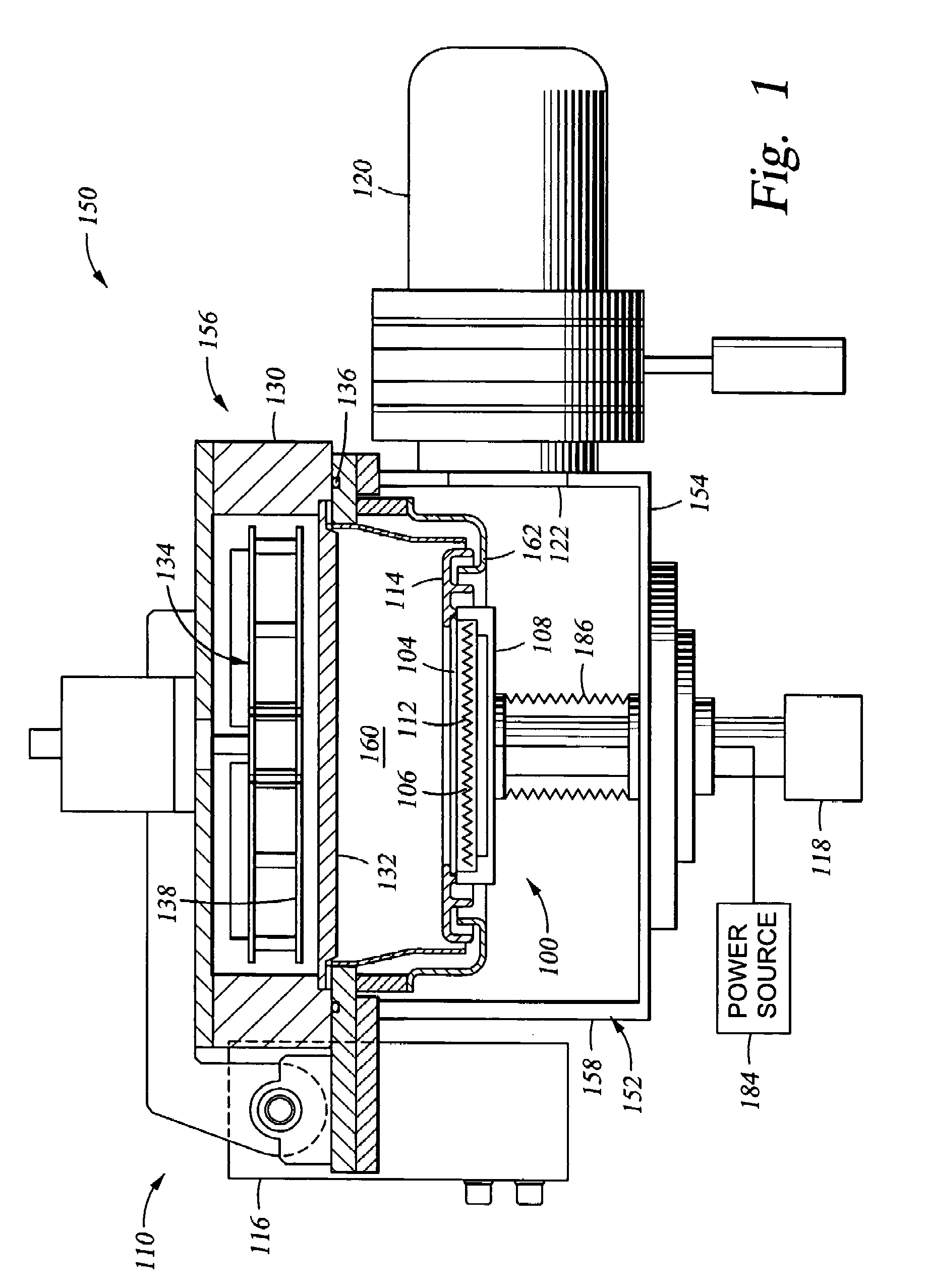
[0026]FIG. 1 depicts one embodiment of a semiconductor processing chamber 150. One example of a processing chamber that may be adapted to benefit from the invention is an IMP VECTRA™ PVD processing chamber, available from Applied Materials, Inc., of Santa Clara, Calif.

[0027]The exemplary processing chamber 150 includes a chamber body 152 having a bottom 154, lid assembly 156 and sidewalls 158 that define an evacuable interior volume 160. The chamber body 150 is typically fabricated from welded plates of stainless...


PUM


Abstract

A semiconductor processing chamber having a motorized lid is provided. In one embodiment, the semiconductor processing chamber generally includes a chamber body having sidewalls and a bottom defining an interior volume. A lid assembly is coupled to the chamber body and is movable between a first position that encloses the interior volume and a second position. A hinge assembly thereto is coupled between the lid assembly and the chamber body. A motor is coupled to the hinge assembly to facilitate moving the lid assembly between the first position and the second position.

Description

CROSS REFERENCE TO OTHER RELATED APPLICATIONS[0001]This application is a continuation of U.S. patent application Ser. No. 10 / 053,296 filed Jan. 17, 2002, now U.S. Pat. No. 6,776,848, incorporated by reference in its entirety.BACKGROUND OF THE INVENTION[0002]1. Field of the Invention[0003]Embodiments of the invention generally relate to a semiconductor processing chamber having a motorized chamber lid.[0004]2. Description of the Related Art[0005]Semiconductor wafer processing is generally performed in vacuum chambers having lid assemblies that may be opened for maintenance and replacement of process kits. In processing chambers configured for 200 mm and smaller substrates, these lid assemblies generally are opened manually. In larger systems, the lid assemblies may weigh in excess of 300 pounds. The weight of these lid assemblies has led to the incorporation of spring, gas pots and counterbalances for facilitating the opening and closing of the lid assembly.[0006]One typical arrangem...

Claims


Application Information

Patent Timeline
IPC IPC(8): C23C16/00C23C14/00C25B11/00H01L21/00C23C14/35C23C16/44E05F15/12H01J37/32
CPCC23C14/35C23C16/44H01J37/32458E05F15/622E05Y2900/00E05F15/614E05Y2900/60E05Y2999/00
Inventor ROSENSTEIN, MICHAELSHENDEROVICH, ALEXSCHWEITZER, MARC O.LAVITSKY, ILYALAU, ALVINFELTSMAN, MICHAEL
Owner APPLIED MATERIALS INC
Why Eureka
Eureka Blog
Learn More