Sample carrier having releasable locking mechanism

a locking mechanism and sample carrier technology, applied in the field of sample carriers, can solve the problems of exposing practitioners to possible repetitive motion injuries and the difficulty of controlling sample carriers, and achieve the effect of limiting carryover contamination and more accurate pipetting

Active Publication Date: 2006-11-07
GEN PROBE INC
View PDF150 Cites 42 Cited by
  • Summary
  • Abstract
  • Description
  • Claims
  • Application Information

AI Technical Summary

Benefits of technology

[0019]Each sleeve of the present invention preferably includes a slot formed therein which is constructed and arranged to permit viewing or scanning of a machine readable label, such as a bar code, affixed to an inserted sample tube. The label may convey information about the source of a test sample or, by way of example, it may instruct an automated test instrument to perform a particular assay protocol on the test sample. In addition, the slot formed in each sleeve and a corresponding opening formed for receiving an adjacent spring therethrough may be configured and aligned to permit viewing or scanning of a machine readable label affixed to a side wall of the support wall above the adjacent spring when a sample tube is not present in a sleeve, thereby providing information about the presence or absence of a sample tube in the corresponding sample tube receiving area.
[0020]In yet a further embodiment of the present invention, the sample carrier further comprises a top wall which is joined to the support wall. The top wall extends laterally and overhangs each aperture in the top member of each sample tube receiving structure. The overhangs function as failsafes when the sample tube receiving structures are locked relative to the support wall by limiting the vertical distance that sample tubes can be unintentionally withdrawn from sample tube receiving areas. Bottom surfaces of the overhangs are vertically higher than top surfaces of sample tubes inserted into the sample tube receiving areas so that the sample tube receiving structures can be locked relative to the support wall.
[0021]In another embodiment of the present invention, the sample carrier further comprises one or more fins extending upward from the top wall for maintaining the sample carrier under a drip shield when an automated pipettor withdraws a pipette tip from a sample tube present in one of the sample tube receiving areas. In this embodiment, an automated sample carousel may advance the sample carrier under a drip shield having holes formed therein for accessing sample tubes present in a sample carrier. As used herein, a “drip shield” is any canopy-like structure under which a sample carrier may be conveyed and which includes through-holes for accessing sample tubes with a robotic pipettor, where the drip shield is constructed and arranged to limit carryover contamination between sample tubes present in the sample carrier. An example of a drip shield is disclosed by Ammann et al., “Automated Process for Isolating and Amplifying a Target Nucleic Acid Sequence,” U.S. Pat. No. 6,335,166. In a preferred mode, the fin or fins are longitudinally or arcuately centered on the top wall and a top surface of the fin or fins are operatively positioned near a bottom surface of the drip shield, preferably about 0.125 inches (3.18 mm) below the bottom surface of the drip shield. The distance between the bottom surface of the drip shield and the top surface of the fin or fins should be less than the depth of a well or other holding structure for maintaining the sample carrier on a sample carousel or other conveying means. This is so that a sample carrier cannot be removed from the well or other holding structure should the penetrable components of a sample tube bind a pipette tip as it is being withdrawn from the sample tube. When the fin or fins make contact with the drip shield, the force that the drip shield exerts against the sample carrier should be sufficient to release the pipette tip from the sample tube so that the sample carrier remains in its holding structure.
[0022]In still another embodiment of the present invention, each aperture is dimensioned, and each associated sample tube receiving area is configured, so that a fully inserted sample tube is substantially immobilized. Immobilization of sample tubes is important since, in a preferred mode, the sample tubes include penetrable caps which are pierced by, for example, conventional plastic pipette tips before test sample is withdrawn from the sample tubes. Centering the pipette tips prior to puncturing the caps helps to limit the forces required to pierce the caps and can provide for more accurate pipetting. In a preferred embodiment, the sample tubes are centered for cap piercing to within about 0.125 inches (3.18 mm) from the longitudinal axis of a top surface of the cap component of the sample tube and more preferably to within about 0.1 inches (2.54 mm).

Problems solved by technology

Amplification, however, raises concerns about cross-contamination, since transferring even a minute amount of target-containing sample to a target-negative sample could lead to the production of billions of target sequences in the “negative” sample, possibly resulting in a false-positive that might otherwise have been negative in the absence of an amplification step.
And the greater the retaining force, the more force practitioners must exert to insert sample tubes into conventional sample carriers, making the sample carriers more difficult to control and exposing practitioners to possible repetitive motion injuries, such as carpal tunnel syndrome.

Method used


Image

  • Sample carrier having releasable locking mechanism
  • Sample carrier having releasable locking mechanism
  • Sample carrier having releasable locking mechanism

Examples


Embodiment Construction

[0049]While the present invention may be embodied in a variety of forms, the following description and accompanying drawings are merely intended to disclose some of these forms as specific examples of the present invention. Accordingly, the present invention is not intended to be limited to the forms or embodiments so described and illustrated. Instead, the full scope of the present invention is set forth in the appended claims.

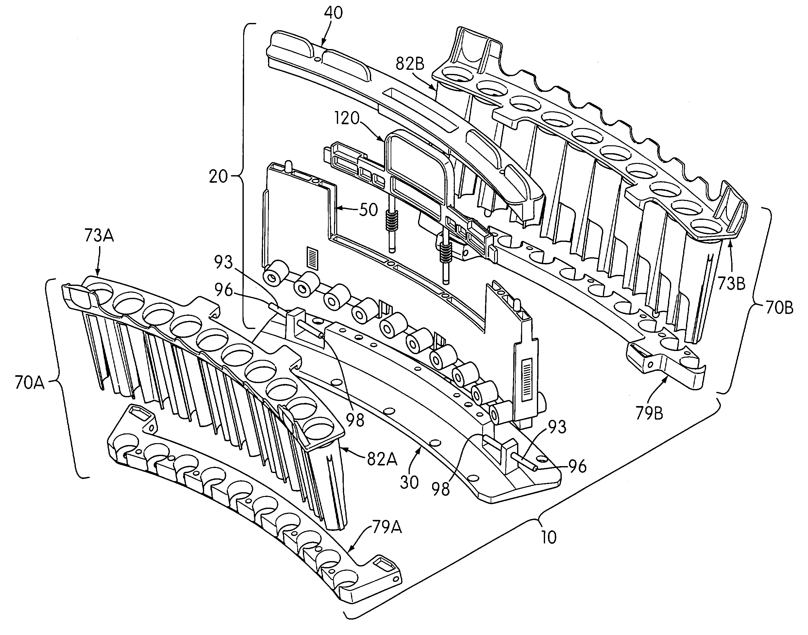
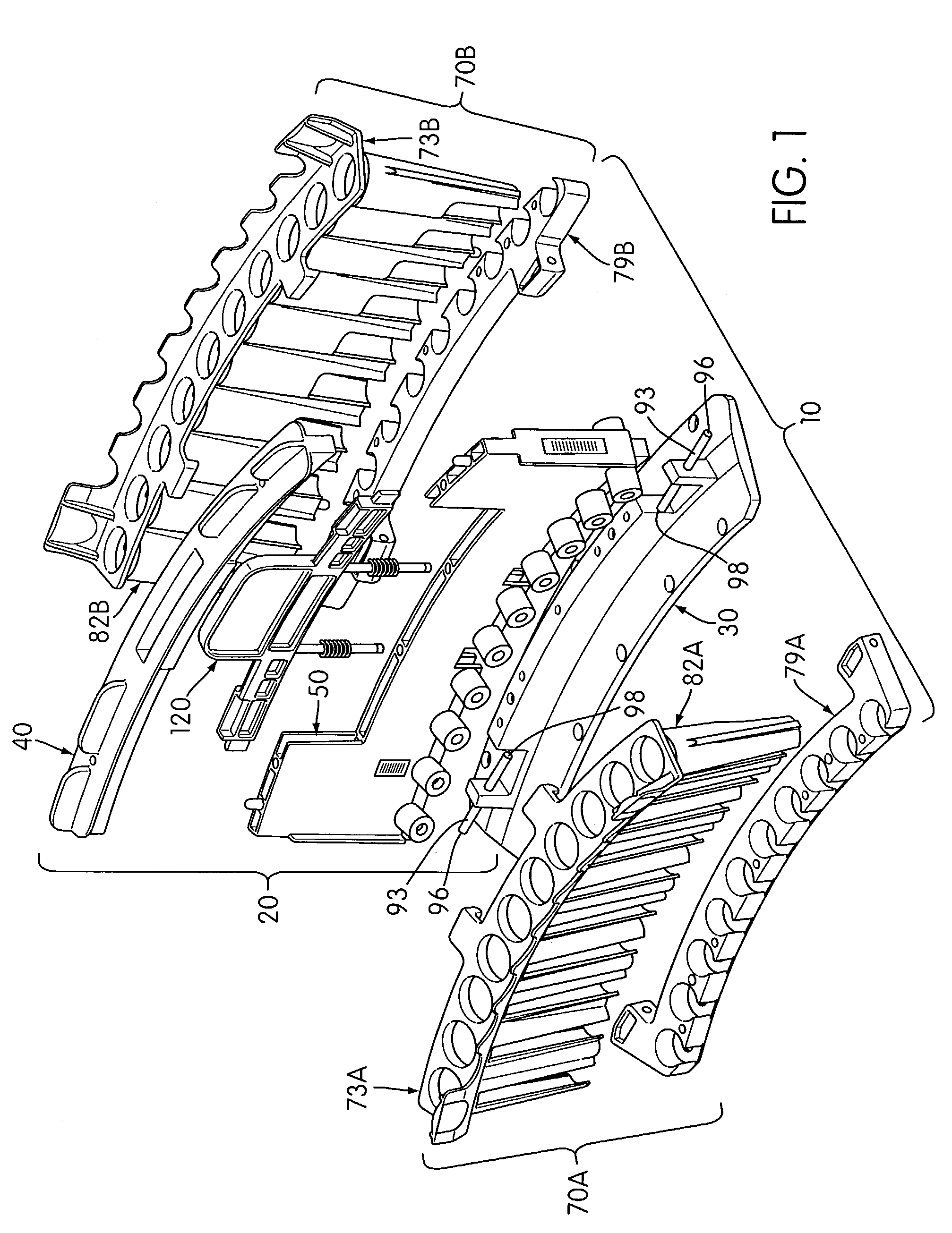
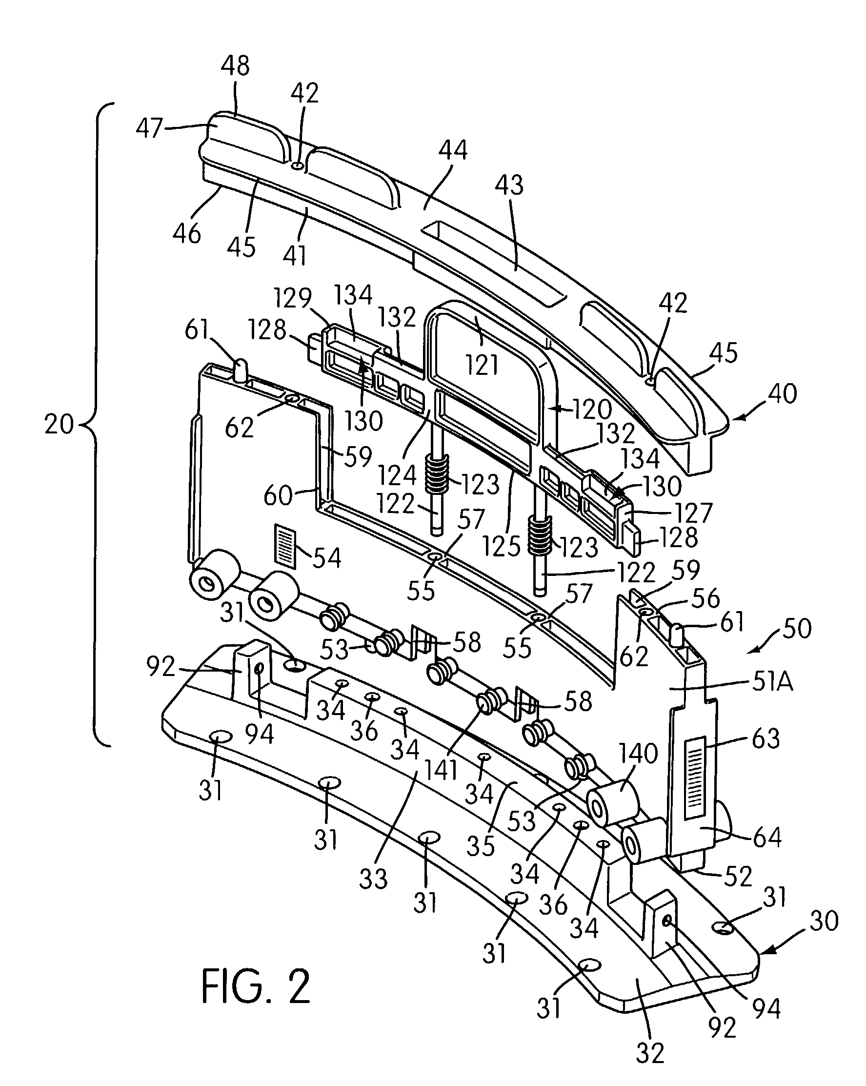
[0050]With reference to the figures, a preferred sample carrier 10 of the present invention is shown alone or in combination with a drip shield 200 for protecting against cross-contamination between sample tubes 300 carried by the sample carrier and for limiting vertical movement of the carrier when test sample is being removed from any of the sample tubes. Sample carriers 10 of the present invention are preferably used in combination with sample tubes 300 having sealed caps 310 which can be penetrated by conventional plastic pipette tips. (The seal is indica...


PUM

PropertyMeasurementUnit
distanceaaaaaaaaaa
elastomericaaaaaaaaaa
shapeaaaaaaaaaa

Abstract

A sample carrier comprising a frame and one or more sample tube receiving structures pivotally connected to the frame. Each sample tube receiving structure includes a bottom member adapted to receive a plurality of sample tubes and a top member having a plurality of aligned apertures sized to receive sample tubes therethrough. The sample tube receiving structures can be releasably locked relative to a support wall of the frame, thereby substantially immobilizing sample tubes that are held by the sample carrier.

Description

CROSS-REFERENCE TO RELATED APPLICATIONS[0001]This application claims the benefit of U.S. Provisional Application No. 60 / 381,551, filed May 17, 2002, the entire contents of which are hereby incorporated by reference herein.FIELD OF THE INVENTION[0002]The present invention relates to a sample carrier for receiving and immobilizing a plurality of sample tubes. The sample carrier of the present invention can be used in conjunction with an automated sampling system and is especially useful with sample tubes having penetrable caps. The present invention further relates to a method for obtaining a test sample from a sample tube which is immobilized in a sample carrier. The method of the present invention is particularly suited for use with sample tubes having penetrable caps.INCORPORATION BY REFERENCE[0003]All references referred to herein are hereby incorporated by reference in their entirety. The incorporation of these references, standing alone, should not be construed as an assertion o...

Claims


Application Information

Patent Timeline
Patent Type & Authority Patents(United States)
IPC IPC(8): B01L9/00G01N35/04B01L3/14B01L9/06C12M1/00C12N15/09G01N35/02
CPCG01N35/025B01L9/06B01L3/50825Y10T436/113332B01L2200/023B01L2200/025B01L2200/0615B01L2200/141B01L2300/021B01L2300/041G01N2035/0448G01N2035/0451G01N2035/0465Y10T436/25625Y10T436/2575Y10T436/114165
Inventor AVILES, ROBERT C.TALMER, MARK A.SEVIGNY, GERARD J.WEBB, MATTHEW W.TSEO, GUS G.
Owner GEN PROBE INC
Why Eureka
Try Eureka