Fastener driving device

Inactive Publication Date: 2006-11-14
STANLEY FASTENING SYST LP
View PDF20 Cites 49 Cited by
  • Summary
  • Abstract
  • Description
  • Claims
  • Application Information

AI Technical Summary

Benefits of technology

[0006]An aspect of the present invention is to fulfill the need expressed above. The underlying concept of the invention is to fundamentally change the device from one in which dry firing is prevented by locking the contact trip assembly in its extended position to one which enables the contact trip assembly to be moved from its extended position into its actuated position under extreme situations where damage is likely, as for example, when the tool is dropped and lands on the extended contact trip element in such a way as to bend or otherwise damage it.
[0011]In accordance with aspects of the present invention, the fulfillment of the expressed need is achieved by providing a fastener driving device. The device includes a portable housing assembly that defines a fastener drive track, a fastener driver that is movably mounted in the drive track, a magazine assembly that is constructed and arranged to feed successive leading fasteners from a supply of fasteners contained therein along a feed track and into the drive track, and a power operated system that is constructed and arranged to be actuated so as to move the fastener driver through successive operative cycles. Each cycle includes a drive stroke in which a fastener in the drive track is driven into a workpiece, and a return stroke. The device also includes an actuating mechanism that includes a contact trip assembly and a trigger assembly that is constructed and arranged to actuate the power operated system in response to a predetermined cooperative movement between the contact trip assembly and the trigger assembly, and a fastener depletion sensing system that is constructed and arranged to allow normal operation of the power system so long as the supply of fasteners provided by the magazine assembly is such that more than a predetermined number of fasteners are in the feed track and / or the drive track. The fastener depletion sensing system is operable, when the predetermined number of fasteners in the feed track and / or the drive track is reached, to provide a tactile indication to the user that the predetermined number of fasteners has been reached, and permitting the user to either cease further operation following the indication or complete the operation following the indication.
[0012]According to an aspect, a fastener driving device is provided. The fastener driving device includes a portable housing assembly that defines a fastener drive track, a fastener driver that is movably mounted in the drive track, a magazine assembly that is constructed and arranged to feed successive leading fasteners from a supply of fasteners contained therein along a feed track and into the drive track, and a power operated system that is constructed and arranged to be actuated so as to move the fastener driver through successive operative cycles. Each cycle includes a drive stroke wherein a fastener in the drive track is driven into a workpiece and a return stroke. The device also includes an actuating mechanism that includes a contact trip assembly and a trigger assembly constructed and arranged to actuate the power operated system in response to a predetermined cooperative movement between the contact trip assembly and the trigger assembly. The contact trip assembly is constructed and arranged to be moveable between an inoperative position and an operative position with an application of a force thereon. The device further includes a fastener depletion sensing system that includes at least two surfaces that engage one another to prevent actuation of the power operated system upon a predetermined amount of fasteners in the feed track and / or the drive track being reached. A further application of force to the contact trip assembly after the indication allows the surfaces to slide past one another so that the contact trip assembly is able to move to the operative position, thereby protecting the contact trip assembly upon the further application of force.

Problems solved by technology

However, the resistance will yield and permit actuation of the contact trip assembly under extreme unwanted accidental actuation situations that are beyond normal, such as the dropping of the tool.

Method used


Image

  • Fastener driving device
  • Fastener driving device
  • Fastener driving device

Examples


Embodiment Construction

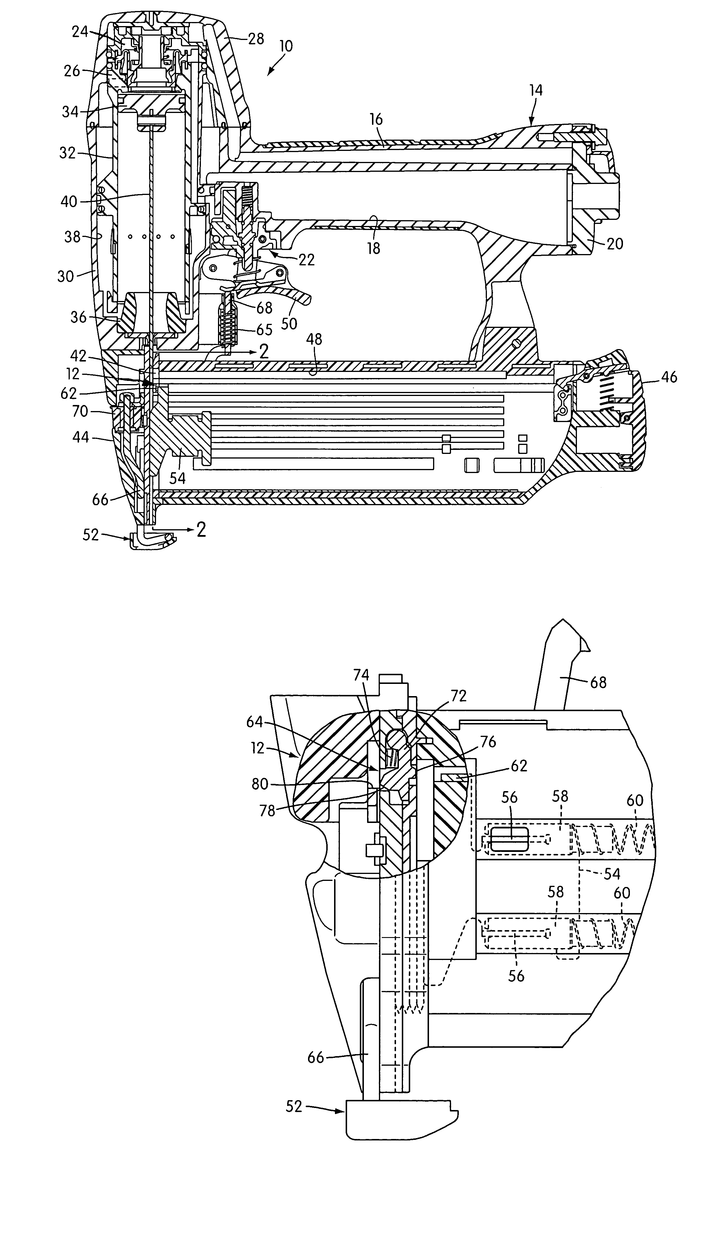
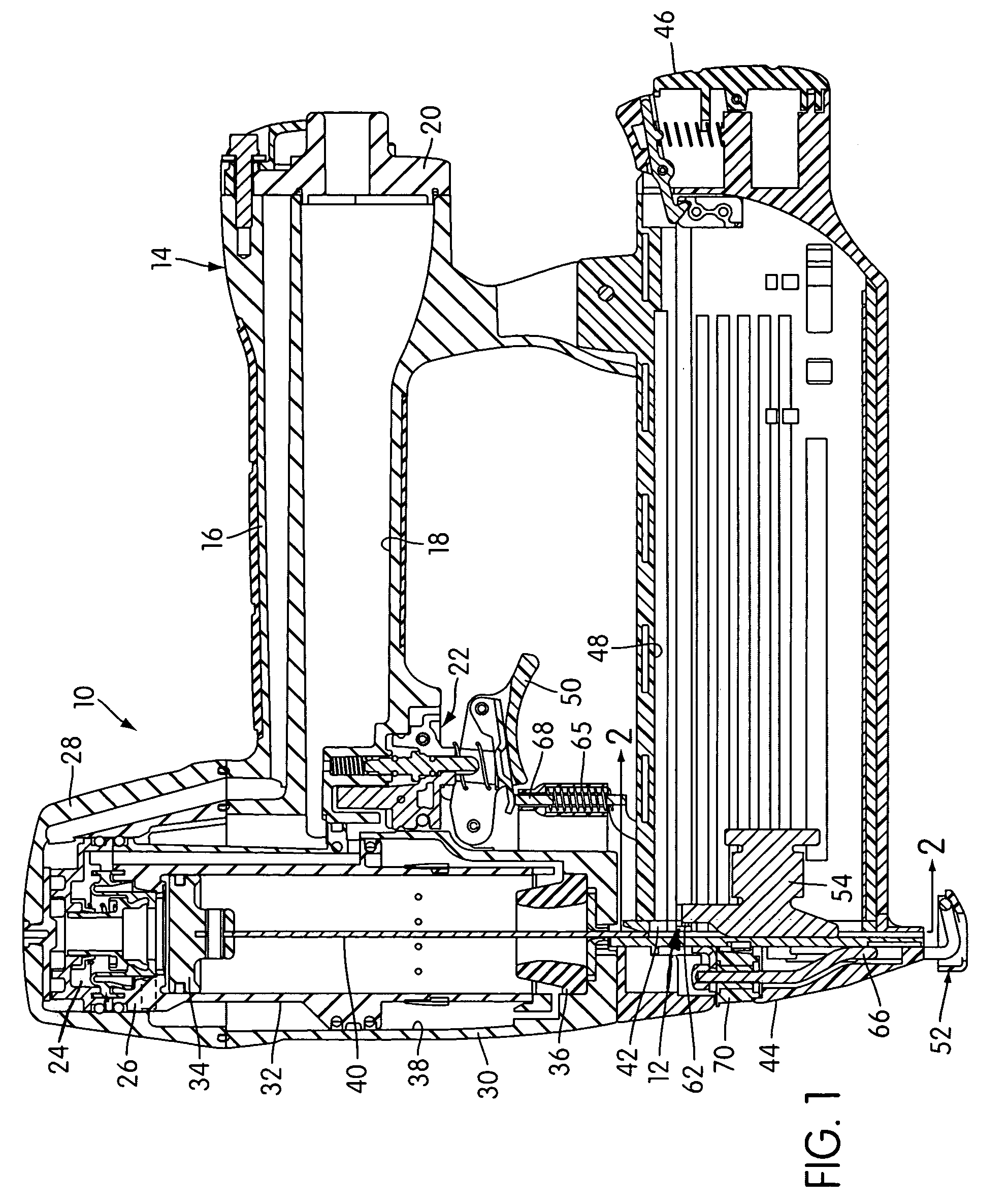
[0023]Referring now more particularly to the drawings, there is shown in FIG. 1 a fastener driving device, generally indicated at 10, embodying the principles of the present invention. The invention is particularly concerned with the construction and operation of a fastener depletion sensing system, generally indicated at 12 and shown in greater detail in FIGS. 4–7, embodied in the fastener driving device 10. The fastener driving device 10 itself may be of any known configuration. As shown, the fastener driving device 10 is power operated. Such power operation can be of any well known type such as electrical, internal combustion or pneumatic. The fastener driving device 10 as shown in FIG. 1 is a typical pneumatically powered unit.

[0024]Specifically, the pneumatically powered fastener driving device 10 shown in FIG. 1 includes a portable housing or frame assembly, generally indicated at 14. The portable housing assembly 14 includes a handle section 16 which is hollow so as to define...


PUM

PropertyMeasurementUnit
forceaaaaaaaaaa
resistanceaaaaaaaaaa
pressureaaaaaaaaaa

Abstract

A fastener driving device is disclosed. The device includes a fastener depletion sensing system that is constructed and arranged to allow normal operation of a power system contained within the device so long as a supply of fasteners provided by a magazine assembly is such that more than a predetermined number of fasteners are in a feed track and / or a drive track within the device. The fastener depletion sensing system is operable when the predetermined number of fasteners in the feed and / or the drive track is reached to provide a tactile indication to the user that the predetermined number of fasteners has been reached, and permitting the user to either cease further operation following the indication or complete the operation following the indication.

Description

BACKGROUND OF THE INVENTION[0001]1. Field of the Invention[0002]This application relates to fastener driving devices and more particularly to power operated fastener driving devices having a system for avoiding the problems associated with dry firing.[0003]2. Description of Related Art[0004]Fastener driving devices of the power operated variety can be either pneumatically operated, electrically operated or internal combustion operated. Such devices involve the expenditure of energy at a level which makes it important that each operation constitutes a desired operation for driving a fastener into a workpiece. Much of the available energy is used up in the driving action itself. Consequently, when the device is operated without a fastener in the drive track to be driven, all of the energy normally provided to effect the driving action must be absorbed by the piston hitting the rubber bumper at the end of the drive stroke of the fastener driver. Where a dry firing of this type takes pl...

Claims


Application Information

Patent Timeline
Patent Type & Authority Patents(United States)
IPC IPC(8): B25C1/04
CPCB25C1/005B25C1/008
Inventor MCGEE, DAVID MCANLAS, JR., PRUDENCIO SCALVINO, ALEXANDER J
Owner STANLEY FASTENING SYST LP
Why Eureka
Try Eureka