Circuit for operating voltage range extension for a relay

a relay and operating voltage technology, applied in the direction of circuit-breaking switches, coupling device connections, pulse techniques, etc., can solve the problems of transistor amplifiers, imperfect switches, and contact arcing still occurring, and the contact can be degraded and eventual destruction of contacts

Inactive Publication Date: 2003-12-30
ORMON CORP
View PDF8 Cites 31 Cited by
  • Summary
  • Abstract
  • Description
  • Claims
  • Application Information

AI Technical Summary

Benefits of technology

The invention may also be characterized as an arc suppression system for a relay having at least one pair of normally open contacts, having an energizing coil with at least two leads, and having at least two contact terminals and two coil terminals respectively electrically coupled to each of the contacts and to each of the coil leads. This system comprises a solid state contact shorting switch having two switch leads connected in parallel with the two contact terminals and having a control lead which, when energized with an input signal, causes the switch to effectively short circuit the two contacts of the relay. It further comprises a first timing pulse generator receiving an input signal from at least one of the two coil terminals and responding to a coil energizing signal by generating a first timing pulse which, when applied to the solid state switch's control lead, causes momentary conduction of the switch. It also comprises a circuit tester and coil switch having an input coupled to at least one of the two contact terminals independently of the switch leads of said solid state switch and arranged to signal, by its conductive or nonconductive state, whether the two relay contacts are or are not effectively short circuited by the solid state switch, this coil switch having two switch leads which form an electrically conductive part of one of the two electrical couplings between the coil leads and the coil terminals, such that the coil cannot be energized to close the relay contacts unless the coil switch first verifies the proper operation of the contact shorting switch and its connections to the contact terminals. Also, it further comprises a second timing pulse generator receiving an input signal from at least one of the two coil terminals and responding to the termination of a coil energizing signal by generating a second timing pulse which, when applied to the solid state switch's control lead, causes conduction of the contact shorting switch of sufficient duration to suppress contact opening arcing. The first timing pulse generator may generate a timing pulse of such short duration that some contact closure arcing is permitted to occur, and the circuit tester and coil switch may include a time delay that maintains the coil switch conductive after it is first rendered conductive for sufficient time so that it remains conductive during any brief moment when the contacts are not fully closed following the opening of the contact shorting switch after the circuit testing is completed.
The invention may also be characterized as an arc suppression system for a relay having at least one pair of normally open contacts, having an energizing coil with at least two leads, and having at least two contact terminals and two coil terminals respectively electrically coupled to each of the contacts and to each of the coil leads, which also comprises a solid state contact shorting switch having two switch leads connected in parallel to the two contact terminals and having a control lead which, when energized with an input signal, causes said switch to effectively short circuit the two contacts of the relay, and a timing pulse generator having two inputs receiving input signals respectively from both of the two coil terminals and responding to a signal fluctuation at either of the coil terminals in a direction indicating a cessation of an incoming relay energizing signal by causing conduction of the contact shorting switch of sufficient duration to suppress contact opening arcing. The timing pulse generator may be designed to respond to signal fluctuations at either of the coil terminals in a direction indicating commencement of a relay energization signal by permitting at least a short duration of no arc suppression activity at contact closure time so that some amount of contact closure arcing is permitted to occur. And the timing pulse generator may also be designed to respond to signal fluctuations at either of the coil terminals in a direction indicating commencement of a relay energization signal by momentarily causing the contact shorting switch to short the relay contacts. During this brief shorting of the relay contacts, other test circuits cam be called upon to test the integrity of the contact shorting switch and the coupling of its switch leads to the contact terminals by measuring the degree to which the contact shorting switch is able to short the relay contacts, the test circuit preventing actuation of the relay if there is any doubt about the ability of the contact shorting switch to suppress contact opening arcing.

Problems solved by technology

As the contacts of a relay are opened or closed, there is an electrical discharge called arcing, which may cause heating and burning of the contacts and typically results in degradation and eventual destruction of the contacts over time.
But contact arcing can still occur.
Also, the transistor amplifier, which is not a perfect switch, must be designed to dissipate heat, and it is heated the entire time the load is supplied with current.
Except in low power, low voltage situations, this is not a satisfactory solution.
U.S. Pat. No. 3,075,124 teaches inserting a semiconductor device in series with the relay contacts to suppress arcing, but such an arrangement also introduces the resistance of the semiconductor device into the load current flow path, causing excessive heating of the semiconductor device.
This arrangement also cannot suppress all arcing, and it is dependent upon some minimal arcing to place its arc suppression mechanism into operation.
But because the switch is not actuated before the contacts open, there is still the possibility of contact arcing with this arrangement.
U.S. Pat. No. 4,745,511 by Kugelman shorts the contacts momentarily with a MOSFET from the moment when the relay coil is first actuated until sometime after the contacts have opened, but this arrangement requires extra power supply connections and thus cannot be built into a relay without the addition of extra power supply pins to the relay housing.
However, Hongel does not teach designing such a system that permits flexibility in how the relay coil is driven by external circuitry.
He also does not teach how such a system can be made fail safe for use with potentially destructive high voltages relative to contact spacing.

Method used


Image

  • Circuit for operating voltage range extension for a relay
  • Circuit for operating voltage range extension for a relay
  • Circuit for operating voltage range extension for a relay

Examples


Embodiment Construction

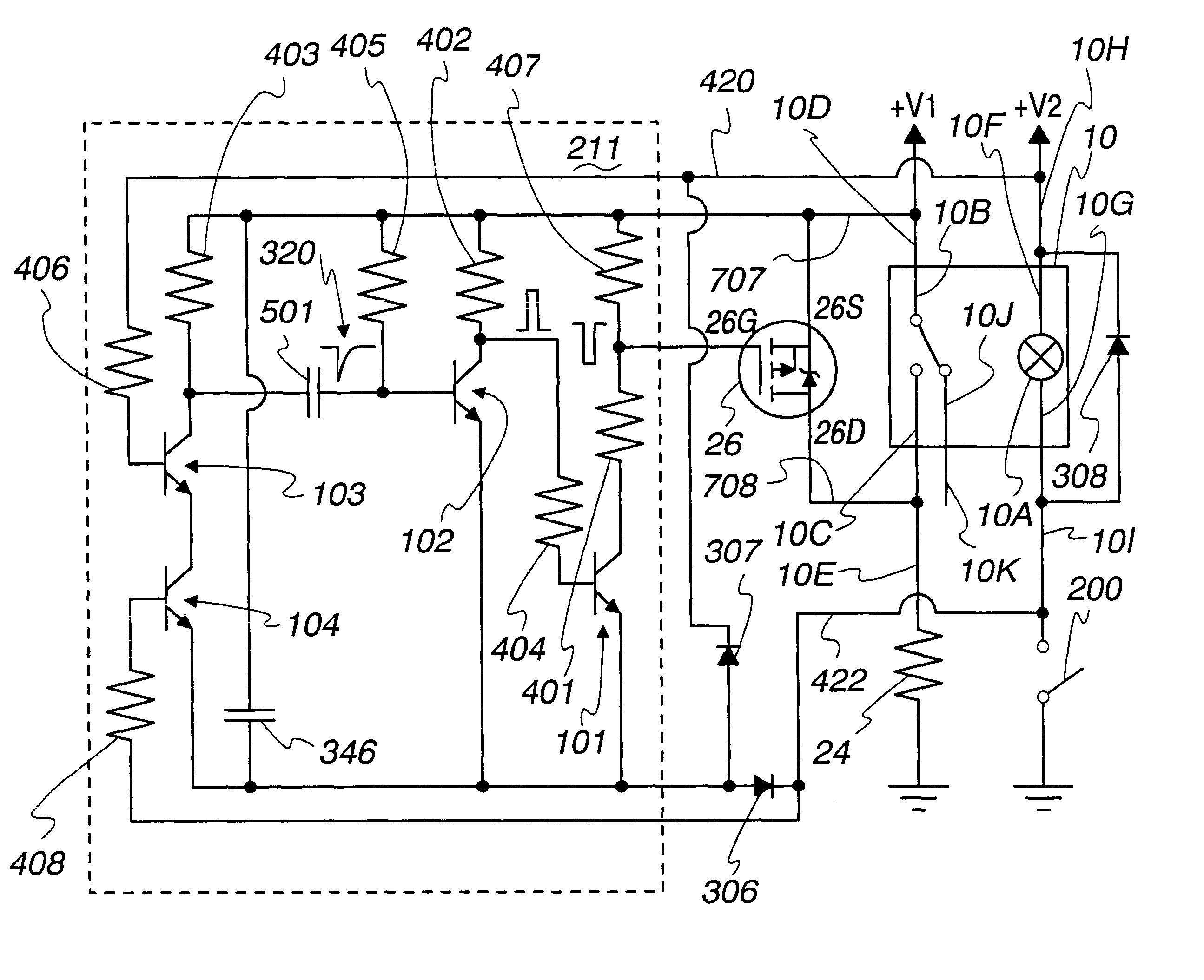
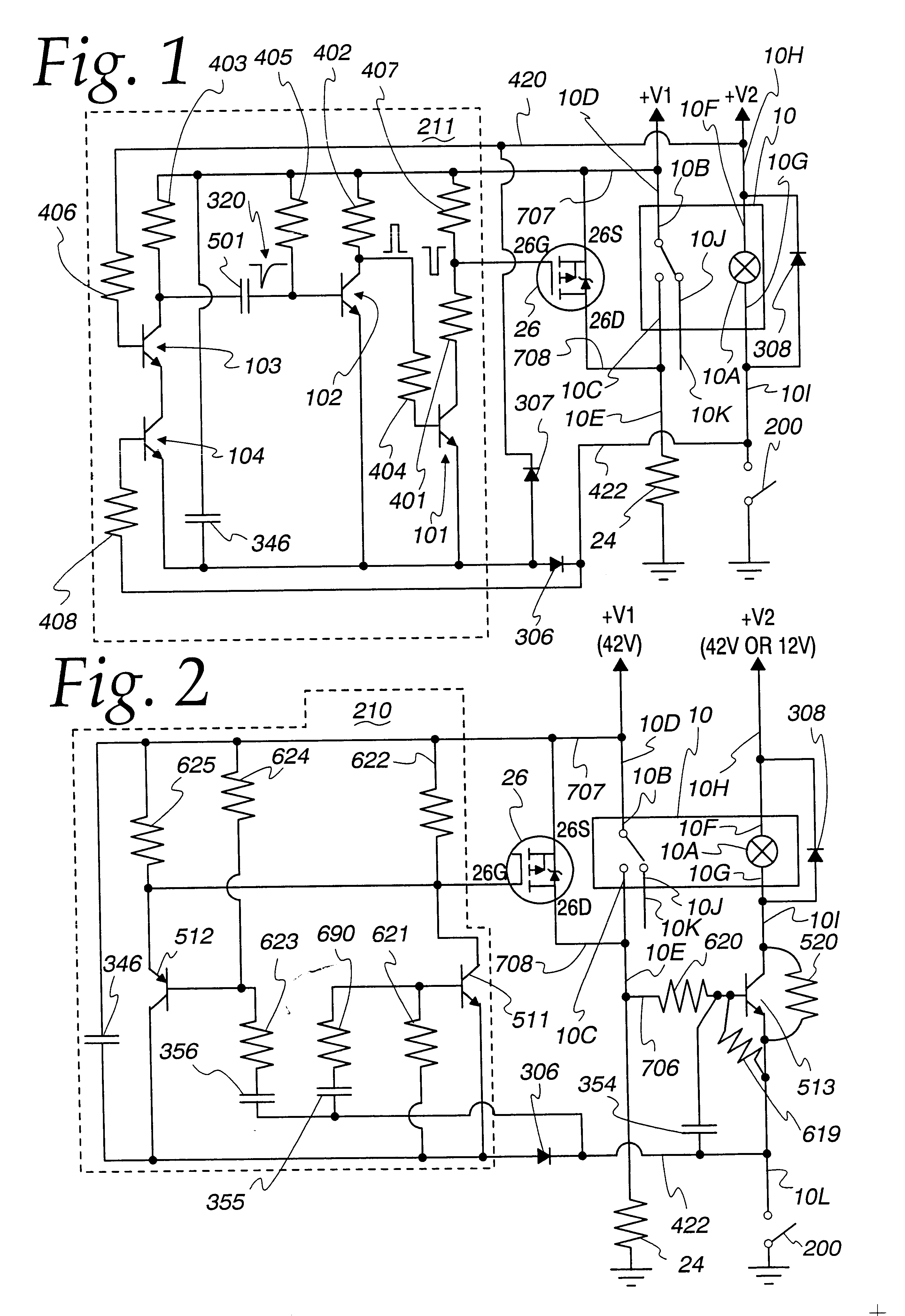
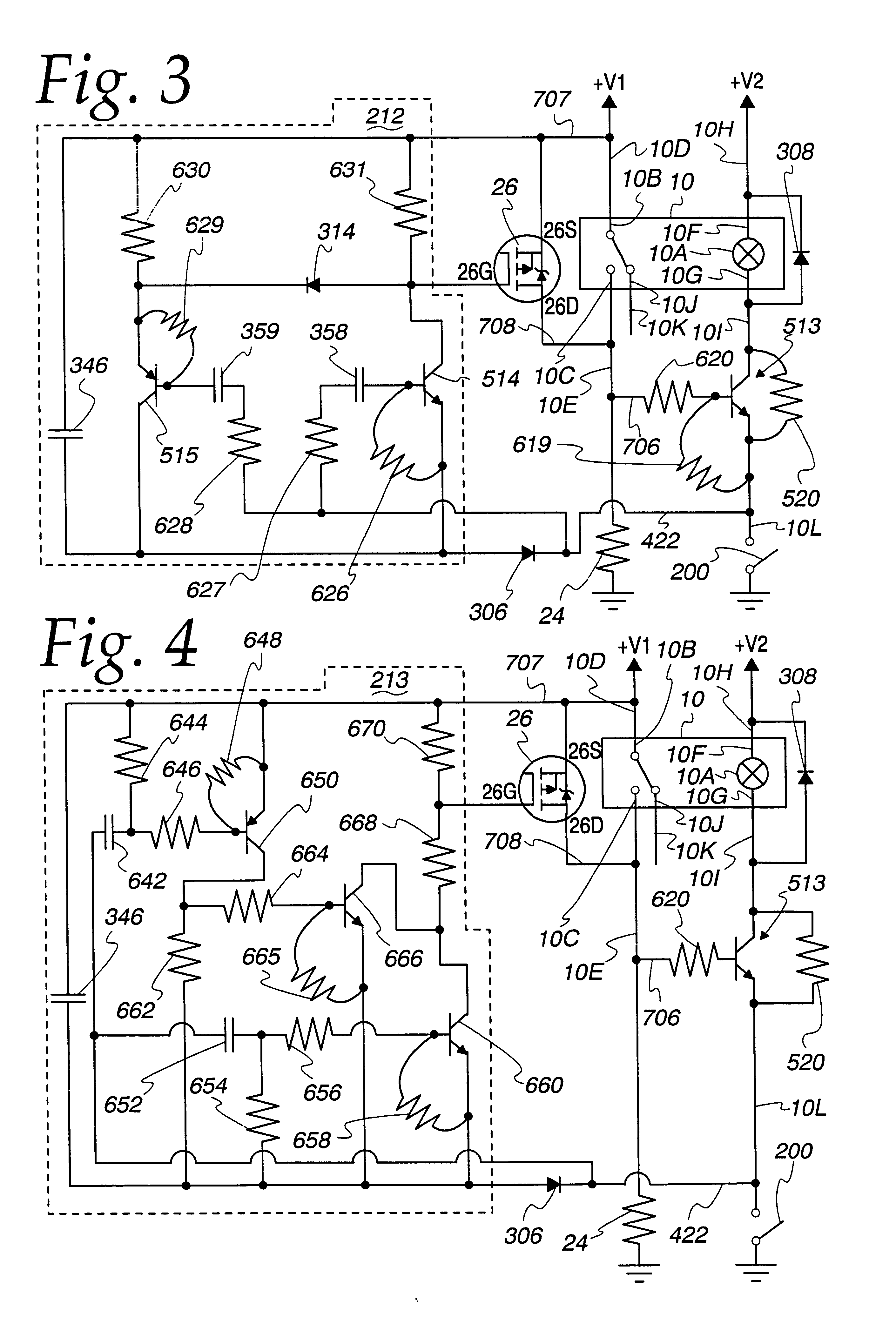
Among other things, the circuitry of the present invention is intended to enable a low-voltage relay 10 to be used safely in higher-voltage environments where the close spacing of the relay contacts 10B and 10C to each other when open might otherwise produce prolonged arcing which could cause a fire if the arc suppression mechanism described below were not present or were to fail. Since the majority of the damage to the contacts 10B and 10C of a relay 10 operating in a high voltage environment occurs during arcing upon the opening of the relay contacts 10B and 10C, as opposed to the closing of the contacts 10B and 10C, the present invention preferably is arranged to provide for arc suppression during the opening of the contacts 10B and 10C, and not necessarily during the closure of the contacts 10B and 10C. Some arcing when the contacts 10B and 10C close can be beneficial in keeping the relay contacts clean and fully operative.

FIG. 1 shows one embodiment of a circuit diagram for an ...


PUM


Abstract

A relay is designed to be used in a circuit where the voltage levels are high in comparison to the spacing between the contacts when open. Contact closure arcing is suppressed by actuating a MOSFET that shorts the contacts together while they open. The same MOSFET can momentarily short the contacts together just before they first begin to close, allowing a test current to be passed through the MOSFET and through the terminals connecting to both relay contacts, to insure that arc suppression will be successful; and if this test fails, then the relay can be disabled by a switch in series with the relay coil to prevent arcing and a possible fire hazard. Relay deactuation can be sensed to trigger arc suppression, and relay actuation can be sensed to initiate fail-safe testing by a circuit that responds no matter which way the relay coil is connected into the external circuit that drives it.

Description

A. Field of the InventionThe present invention relates to relay contact protective circuits and, in particular, to fail-safe arc suppression control circuits that can protect relay contacts.B. Description of the Related ArtA relay is used to perform automatic electrical switching. A relay typically comprises two parts: a coil and a magnetic switch. When an electrical current flows through the coil, a magnetic field is created in proportion to the current flow through the coil. At a predetermined point, the magnetic field is sufficiently strong to pull the switch's movable contact from its rest, or de-energized position, to its actuated, or energized position pressed against the switch's stationary contact. When the electrical power applied to the coil drops, the strength of the magnetic field drops, releasing the movable contact and allowing it to return to its original de-energized position. As the contacts of a relay are opened or closed, there is an electrical discharge called ar...

Claims


Application Information

Patent Timeline
Patent Type & Authority Patents(United States)
IPC IPC(8): H01H9/54H03K17/28H03K17/284H01H1/60H01H1/00H01H50/04H01H50/02H01H47/00H01R13/703H01R13/70
CPCH01H9/542H03K17/284H01H1/605H01H47/002H01H50/048H01R13/7031H01R2201/20H01H50/021
Inventor BECKERT, JAMES J.WITT, PAUL A.ROLLER, MICHAEL J.
Owner ORMON CORP
Why Eureka
Try Eureka