Circuitry for Portable Lighting Devices and Portable Rechargeable Electronic Devices

a rechargeable electronic device and circuit technology, applied in the field of portable electronic devices, can solve the problems of stressing the filament, mechanical switches also do not permit automated or regulated modes of activating and deactivating flashlights, and prone to wear and tear

Inactive Publication Date: 2014-03-13
MAG INSTR INC
View PDF2 Cites 0 Cited by
  • Summary
  • Abstract
  • Description
  • Claims
  • Application Information

AI Technical Summary

Benefits of technology

[0015]Accordingly, in a first aspect of the invention, a portable rechargeable electronic device, such as a flashlight, with external charging contacts and a short protection circuit is provided. The short protection circuit electrically uncouples one of the exposed charging contacts from the rechargeable power supply for the device when the charging contacts are shorted together. The charging contact is uncoupled without opening the power circuit for the device; thus, the device can continue to operate while the charging contacts are shorted. The power supply for the device may be a rechargeable lithium-ion battery pack.
[0018]The short protection circuit may also include a comparing device adapted to compare a voltage of a first input signal to a voltage of a second input signal and open or close the switch based on the comparison. The voltage of the first signal may be proportional to the voltage difference between the first charging contact and ground and the voltage of the second signal may be proportional to the voltage of the power source. The comparing device may, for example, comprise a comparator, an op amp, an ASIC, or a processor. When the voltage drop between the first charging contact and ground is approximately equal to or greater than the voltage of the battery, the switch is commanded to be in the “on” position by the comparing device. As a result, when the device is in its charger energy may flow from the charging contact to the power source. When the voltage drop between the first charging contact and ground is zero, the switch is commanded to be in the “off” position. Thus, if a short occurs between the charging contacts, the switch will be turned “off” or opened. As a result, the power source avoids any short across the charging contacts and can continue to supply power to the power consuming load.
[0019]The rechargeable device may comprise a flashlight, and the DC power source may comprise a rechargeable lithium-ion battery pack. In case of a short across the charging contacts, the short protection circuit may be configured to detect and clear the short faster than the built-in short circuit protection of the lithium-ion battery pack. As such, the short protection circuit ensures that the operation of the device is not interrupted if a short occurs on the external charging contacts. This is particularly advantageous if the rechargeable device comprises a flashlight.
[0021]According to a second aspect of the invention, a portable lighting device that includes a circuit for regulating current flow through the lamp of the device is provided. The circuit preferably reduces the initial surge of current that is sent through the lamp when the lamp is turned on. In the case of lighting devices that employ incandescent lamp bulbs, such a circuit may be used to reduce the stresses placed on the lamp bulb when the lighting device is turned on, thereby extending the life expectancy of the lamp bulb.
[0024]According to another embodiment, the lighting device comprises a flashlight having a main power circuit that includes a power source, a lamp, and an electronic power switch, and a power control circuit electrically coupled to the electronic power switch and adapted to provide a signal to the electronic power switch while the flashlight is on. In the present embodiment, the amount of current the electronic power switch is capable of conducting in the main power circuit is dependent on the voltage of the signal applied to the electronic power switch, and the power control circuit is configured to vary the voltage of the signal in a manner that increases the amount of current that can flow through the power switch over a predetermined period when the flashlight is turned on.

Problems solved by technology

One of the disadvantages of a mechanical switch is that they are prone to wear and tear as well as oxidation of the elements that physically make and break the circuit.
Mechanical switches also do not permit automated or regulated modes of activating and deactivating a flashlight.
Another disadvantage of traditional flashlights is that when they are switched on they instantly allow large amounts of current to flow from the batteries through the lamp filament, thereby stressing the filament.
This surge of current occurs because the resistance of the lamp's filament is very low when the filament is cold.
Although the current surge during this transient stage exceeds the bulb's design limits, the duration of the transient stage is short enough that bulbs generally survive the current surge.
Over time, however, this rush of current causes damage to the lamp by stressing the filament and ultimately failure of the lamp filament.
Indeed, it is generally during this transient stage that a lamp filament will ultimately fail.
Yet another disadvantage of traditional flashlights is that they are generally powered with alkaline or dry cell batteries.
Replacing batteries is an inconvenience and an additional expense to a flashlight user.
Furthermore, alkaline or dry cell batteries are heavy, thereby adding to the overall weight of the flashlight.
They are, however, relatively large and must be refilled with liquid electrolyte after being used for a period of time.
Due to their bulky size and weight, even heavier than alkaline / dry cell batteries, rechargeable lead-acid batteries are usually used with wall-mounted safety lighting fixtures, motorcycles, and automobiles, but are generally not considered suitable for use with portable lighting devices, such as flashlights.
However, these batteries have a disadvantage of causing heavy metal pollution.
However, a lithium-ion battery can explode if it is charged beyond its safe limits, or if its terminals are shorted together.
Further, over discharging a lithium-ion battery can permanently damage the lithium-ion cell.
Unfortunately, such a configuration requires the use of plugs, special inserts, alignment tabs or a complex cradle to recharge the batteries.
Obstructing access to the recharging contacts is not, however, a viable solution in the case of flashlights or other rechargeable devices where design requirements dictate that the charging contacts or rings be exposed.
Such inadvertent interruptions may be dangerous when a user is working in an unlit area, especially for law enforcement and emergency response personnel.
And, while a simple diode can be placed in the recharging circuit to prevent accidental short circuits from being created across the charging rings or contacts for other rechargeable battery chemistries, such as nickel-cadmium and nickel metal hydride, this solution is not viable for lithium-ion battery packs.
A simple diode cannot be used in these circumstances because the forward voltage drop of a diode varies greatly while charging lithium-ion batteries requires very tight control over the termination voltage.
In view of the foregoing, rechargeable lithium-ion battery technology has not been adopted for use in portable electronic devices with exposed charging contacts, such as rechargeable flashlights.

Method used


Image

  • Circuitry for Portable Lighting Devices and Portable Rechargeable Electronic Devices
  • Circuitry for Portable Lighting Devices and Portable Rechargeable Electronic Devices
  • Circuitry for Portable Lighting Devices and Portable Rechargeable Electronic Devices

Examples


Embodiment Construction

[0048]To facilitate the description of the invention, any reference numeral representing an element in one figure will represent the same element in any other figure.

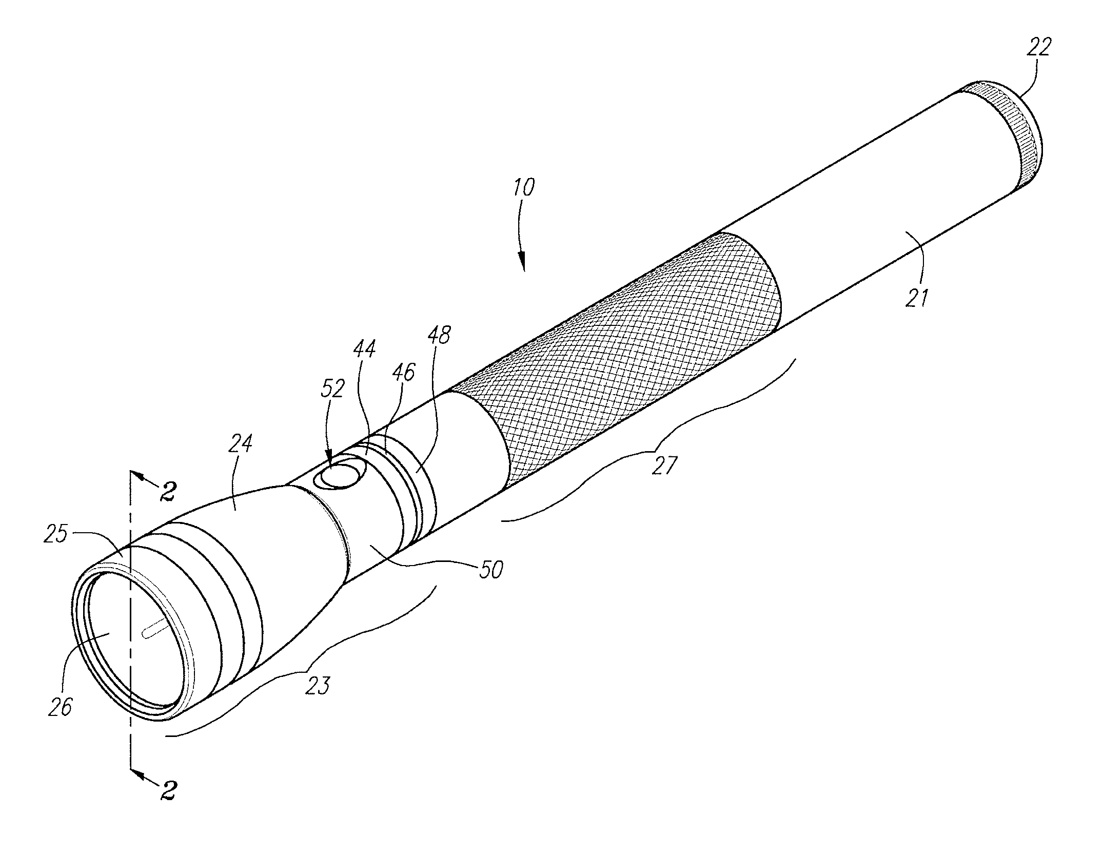
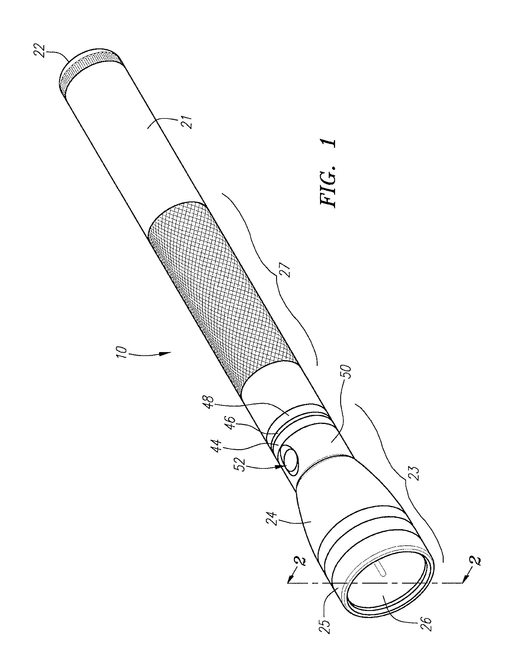
[0049]A flashlight 10 according to one embodiment of the present invention is illustrated in perspective in FIG. 1. The flashlight 10 incorporates a number of distinct aspects of the present invention. While these distinct aspects have all been incorporated into the flashlight 10, it is to be expressly understood that the present invention is not restricted to flashlight 10 described herein. Rather, the present invention is directed to each of the inventive features of the flashlight described below individually as well as collectively. Further, as will become apparent to those skilled in the art after reviewing the present disclosure, one or more aspects of the present invention may also be incorporated into other electronic devices, including cell phones, portable radios, toys, as well as other non-portable lighting d...


PUM


Abstract

A portable electronic device, such as a flashlight, with a circuit for reducing the initial surge of current that is sent through the lamp filament when a flashlight is turned on is provided. The circuit reduces the stresses placed on the lamp bulb when it is turned on, thereby extending the life expectancy of the lamp bulb. A flashlight with beacon mode that produces light according to a duty cycle of less than 11% is also disclosed.

Description

CROSS REFERENCE TO RELATED APPLICATIONS[0001]This application is a continuation of U.S. patent application Ser. No. 13 / 373,802, filed Jan. 20, 2010, which is a continuation of U.S. patent application Ser. No. 11 / 351,307, filed Feb. 8, 2006, which is a continuation-in-part of U.S. patent application Ser. No. 11 / 007,771, filed Dec. 7, 2004, now U.S. Pat. No. 7,579,782. The foregoing applications are incorporated by reference as if fully set forth herein.FIELD OF THE INVENTION[0002]The field of the present invention relates to portable electronic devices, including hand held portable lighting devices, such as flashlights, and their circuitry.BACKGROUND[0003]Various hand held or portable lighting devices, including flashlight designs, are known in the art. Flashlights typically include one or more dry cell batteries having positive and negative electrodes. In certain designs, the batteries are arranged in series in a battery compartment of a barrel or housing that can be used to hold th...

Claims


Application Information

Patent Timeline
Patent Type & Authority Applications(United States)
IPC IPC(8): H05B37/02F21Y101/00
CPCH05B37/02F21L4/00F21L4/005F21L4/08F21V23/0414H02J7/0031H05B39/02H02J7/00304H05B47/165H05B47/17H02J7/00302H02J7/00306F21L4/085H05B47/10H02J7/0029
Inventor WEST, STACEY H.
Owner MAG INSTR INC
Why Eureka
Try Eureka