
Surgical instrument sleeve

a surgical instrument and sleeve technology, applied in the field of surgical instruments, can solve the problems of microsurgical instrument tips being bent or broken with very little force, instruments that may be easily damaged, and surgical instruments with dimensions configured for microsurgical procedures are particularly susceptible to damage, so as to increase the stiffness of a portion

Active Publication Date: 2013-08-01
KATALYST SURGICAL
View PDF13 Cites 34 Cited by
  • Summary
  • Abstract
  • Description
  • Claims
  • Application Information

AI Technical Summary

Benefits of technology

The patent text describes a surgical instrument with a protective sleeve and an inner sleeve. The protective sleeve can be extended or retracted to protect the inner sleeve before and after surgery, and can be controlled by applying force to its distal end. A support sleeve can also be used to increase the stiffness of the inner sleeve or prevent it from acting in unexpected directions. The support sleeve can be designed to cause the inner sleeve to actuate in a specific direction, whether it be clockwise or counter-clockwise. Overall, this design allows for better control and protection during surgical procedures.

Problems solved by technology

A variety of surgical procedures are performed with delicate surgical instruments that may be easily damaged even if the instruments are handled in a reasonable manner.
Surgical instruments with dimensions configured for microsurgical procedures are particularly susceptible to damage because microsurgical instruments are typically designed and manufactured to provide surgical utility rather than instrument durability.
For example, microsurgical instrument tips may be bent or broken with very little force.
Even if a microsurgical instrument tip is not bent or broken, routine handling of an instrument may fatigue delicate portions of the instrument making the instrument unfit for use in a surgical procedure.
In addition to being particularly susceptible to damage during routine handling, microsurgical instrument tips may actuate in unexpected directions if the instrument tips are inserted in a cannula.
However, some microsurgical instrument tips, e.g., 25 gauge instrument tips, are not easily actuated within a cannula because the instrument tips are too flexible.

Method used


Image

  • Surgical instrument sleeve
  • Surgical instrument sleeve
  • Surgical instrument sleeve

Examples


Embodiment Construction

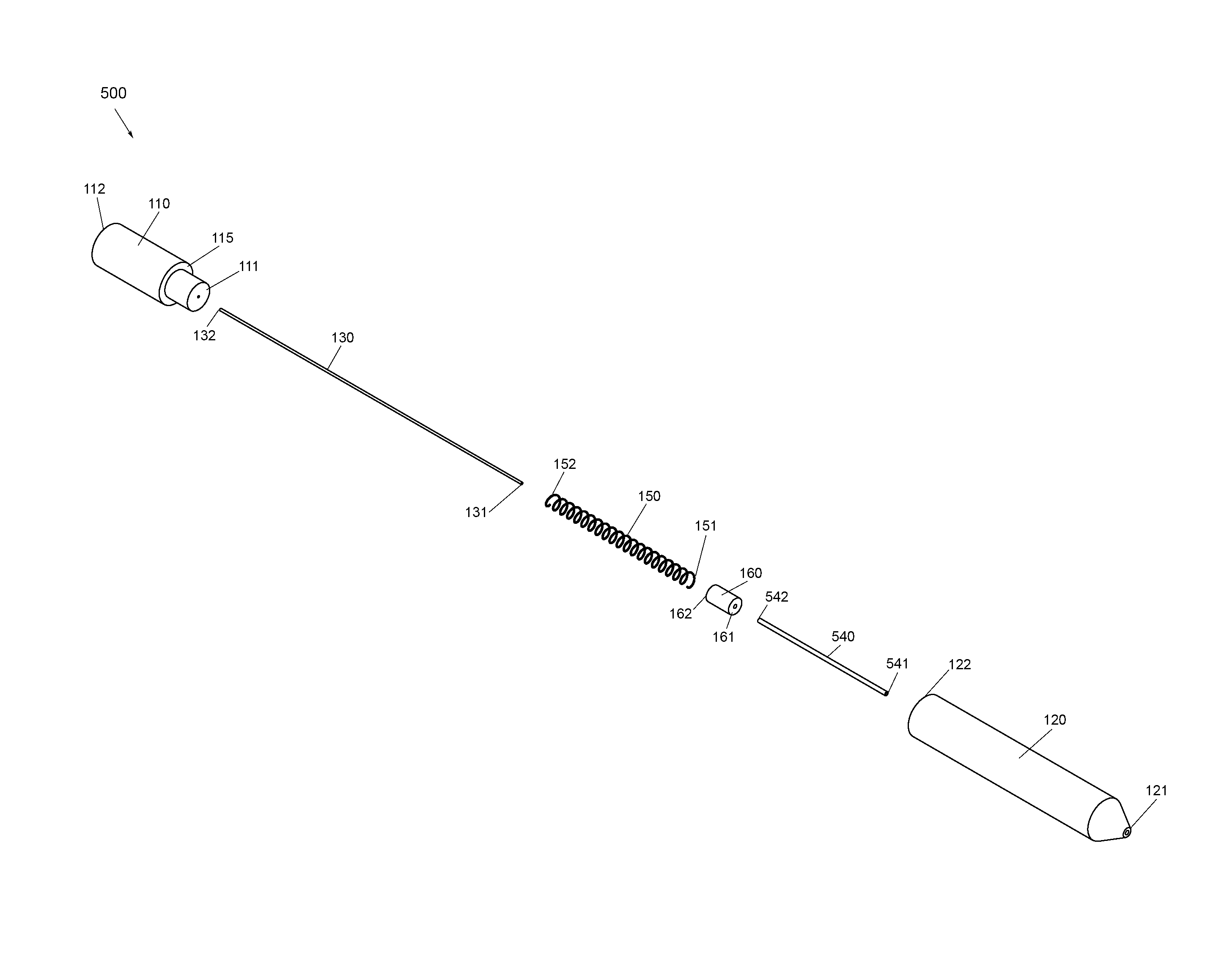
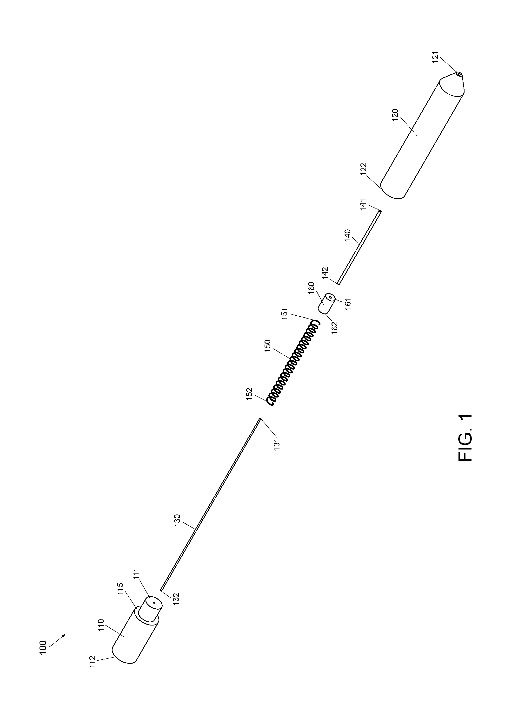
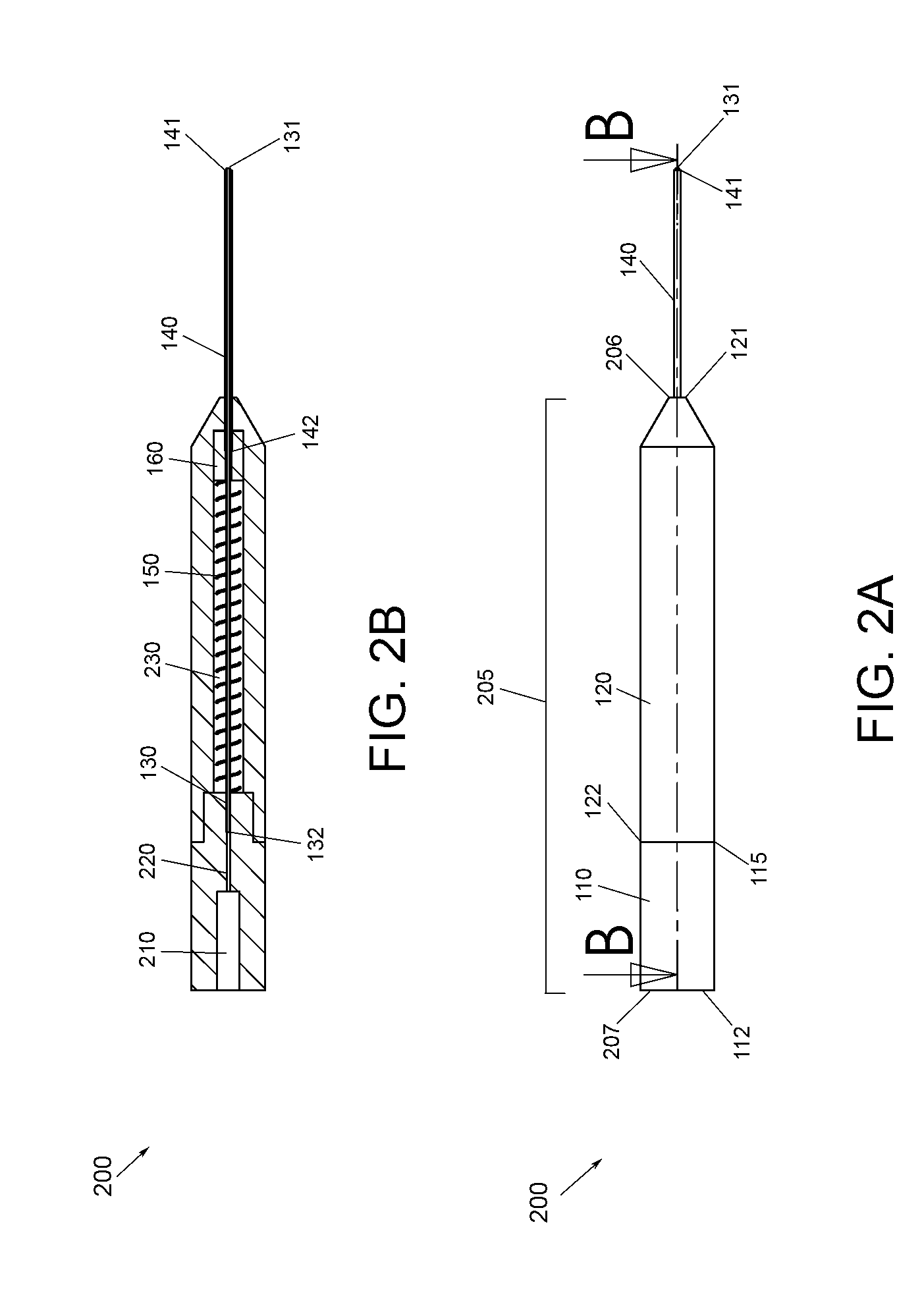
[0015]FIG. 1 is a schematic diagram illustrating an exploded view of a surgical instrument assembly 100. In one or more embodiments, a surgical instrument assembly 100 may comprise a handle base component 110 having a handle base component distal end 111 and a handle base component proximal end 112, a handle base 120 having a handle base distal end 121 and a handle base proximal end 122, an inner sleeve 130 having an inner sleeve distal end 131 and an inner sleeve proximal end 132, a protective sleeve 140 having a protective sleeve distal end 141 and a protective sleeve proximal end 142, a pressure mechanism 150 having a pressure mechanism distal end 151 and a pressure mechanism proximal end 152, and a piston 160 having a piston distal end 161 and a piston proximal end 162. Illustratively, handle base component 110 may comprise a handle base interface 115 configured to interface with handle base 120, e.g., at handle base proximal end 122. Handle base component 110, handle base 120, ...


PUM


Abstract

A surgical instrument may have a handle, a support sleeve, and an inner sleeve. Illustratively, the support sleeve may be configured to actuate relative to the inner sleeve to protect the inner sleeve before and after a surgical procedure and to expose a portion of the inner sleeve during the surgical procedure. In one or more embodiments, an application of a force to a distal end of the support sleeve may be configured to retract the support sleeve relative to the inner sleeve. Illustratively, a reduction of a force applied to the distal end of the support sleeve may be configured to extend the support sleeve relative to the inner sleeve.

Description

CROSS-REFERENCE TO RELATED APPLICATIONS[0001]This Application claims the benefit of U.S. Provisional Application No. 61 / 590944, filed Jan. 26, 2012.FIELD OF THE INVENTION[0002]The present disclosure relates to a surgical instrument, and, more particularly, to a surgical instrument sleeve.BACKGROUND OF THE INVENTION[0003]A variety of surgical procedures are performed with delicate surgical instruments that may be easily damaged even if the instruments are handled in a reasonable manner. Surgical instruments with dimensions configured for microsurgical procedures are particularly susceptible to damage because microsurgical instruments are typically designed and manufactured to provide surgical utility rather than instrument durability. For example, microsurgical instrument tips may be bent or broken with very little force. Even if a microsurgical instrument tip is not bent or broken, routine handling of an instrument may fatigue delicate portions of the instrument making the instrumen...

Claims


Application Information

Patent Timeline
Patent Type & Authority Applications(United States)
IPC IPC(8): A61B17/00
CPCA61F9/007A61B17/3496A61B2019/481A61B2017/305A61B2019/4805A61F9/00736A61B2090/0801A61B2090/08021
Inventor SCHELLER, GREGG D.MOORE, CRAIGZEID, MATTHEW N.
Owner KATALYST SURGICAL
Learn More