
Unlocking member arranging structure for vehicles

a technology for unlocking members and arranging structures, applied in the field of vehicles, can solve problems such as being subject to undesirable tampering, and achieve the effect of reducing the risk

Inactive Publication Date: 2006-11-14
HONDA MOTOR CO LTD
View PDF27 Cites 18 Cited by
  • Summary
  • Abstract
  • Description
  • Claims
  • Application Information

AI Technical Summary

Benefits of technology

The present invention provides an unlocking member arranging structure for vehicles that can prevent the unlocking member from releasing the lid from its locked state being tampered with and minimize the risk for the unlocking member to be influenced by external disturbances such as unfavorable weather. The invention also includes a cover member and an unlocking member that are arranged onto an inner cover which covers from behind a head pipe provided on the body frame at its front end and constitutes part of the body cover. The invention further includes a compartment locking mechanism to lock the storage compartment in its fully closed position. The unlocking member is arranged in a position close to the rider's hands for easy manipulation and can be influenced by external disturbances such as unfavorable weather. The invention also includes a drawer-type storage compartment that can be accessed from both sides and a lid that can cover the fuel refill cap, which is frequently used. The invention provides greater space efficiency, reduces the number of components, and improves effectiveness.

Problems solved by technology

However, if part of an unlocking member provided with a keyhole is arranged with part of the unlocking member overlooking the outer face of the body cover as in the conventional configuration mentioned above, it will be subject to undesirable tampering.

Method used


Image

  • Unlocking member arranging structure for vehicles
  • Unlocking member arranging structure for vehicles
  • Unlocking member arranging structure for vehicles

Examples


Embodiment Construction

[0049]A mode for carrying out the present invention will be described below with reference to one embodiment of the invention illustrated in the accompanying drawings.

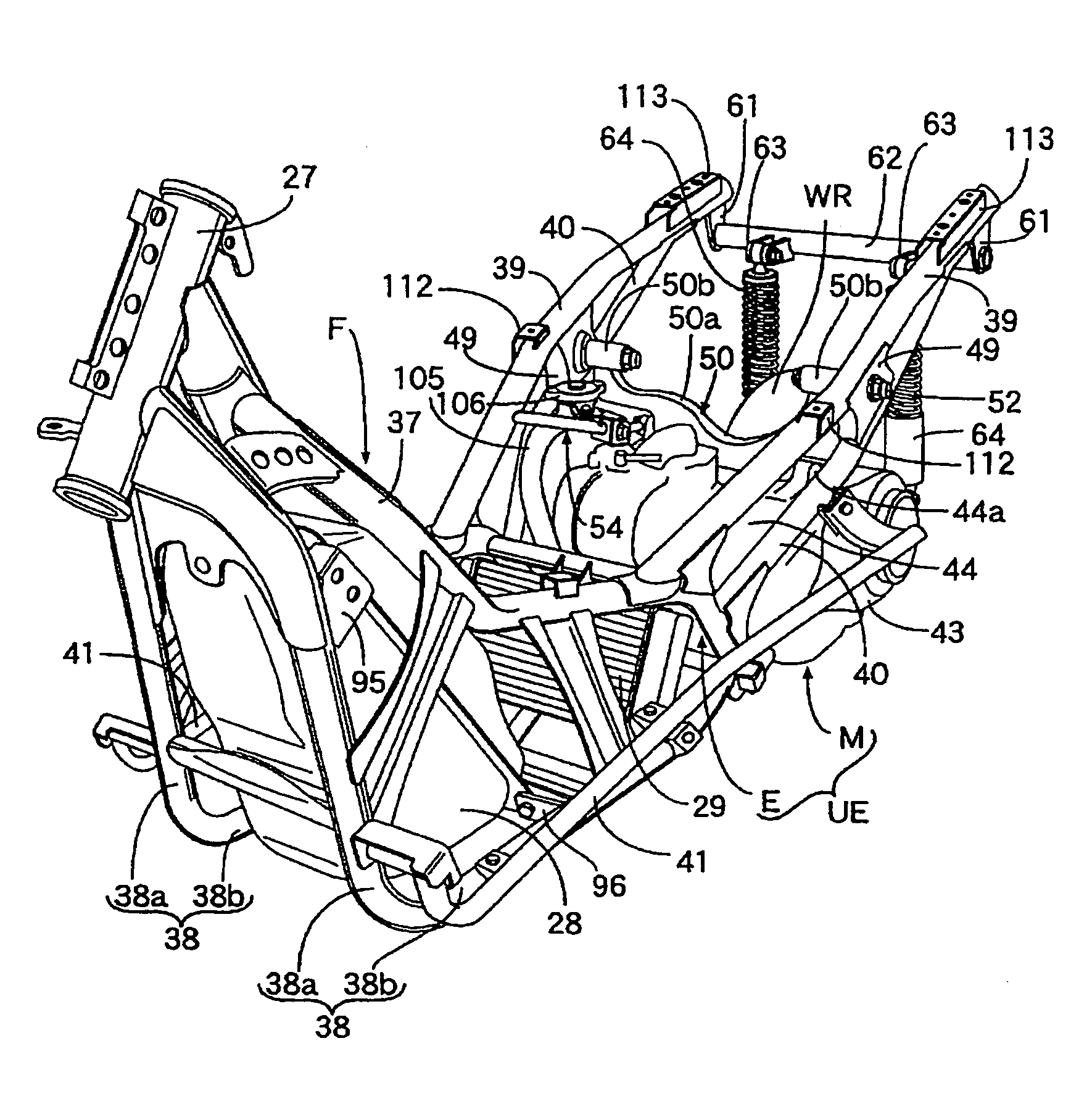
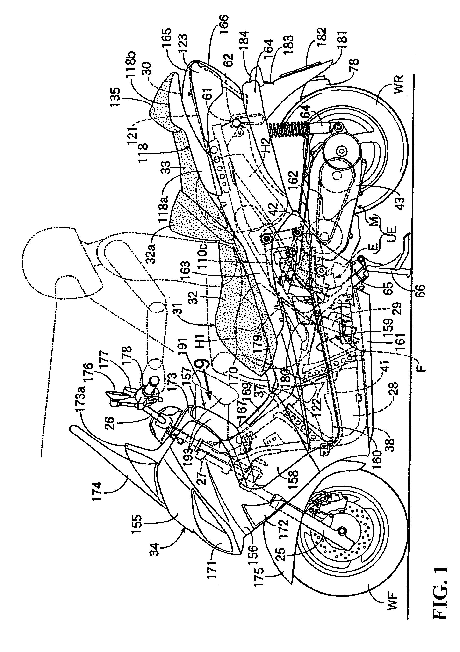
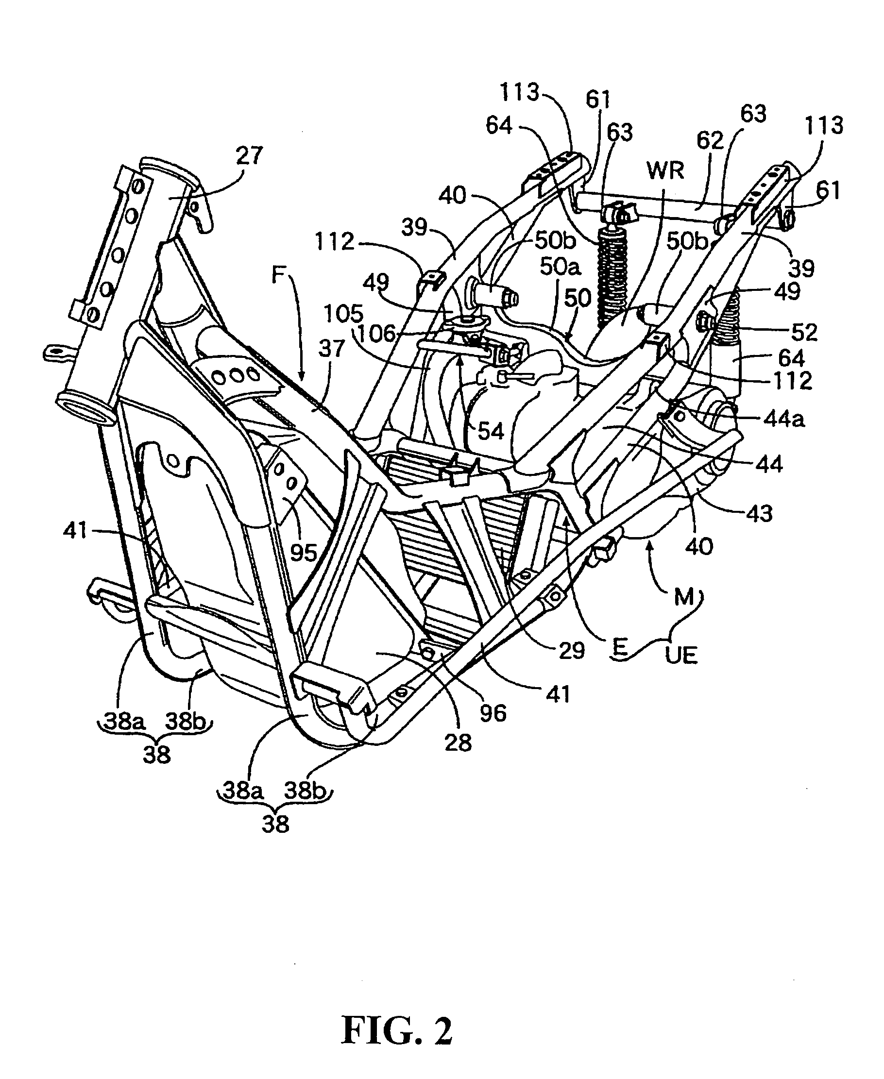
[0050]As illustrated in FIG. 1, the body frame F of a scooter-type motorcycle is provided at its front end with a front fork 25 bearing the shaft of the front wheel WF and a head pipe 27 steerably bearing a steering handlebar 26 linked to the front fork 25. A unit swing engine UE includes a rear end wherein a rear wheel WR is supported to be movable up and down by the central part, in the back-and-forth direction, of the body frame F. The body frame F is mounted farther forward than the unit swing engine UE with a fuel tank 28, which is a functional part formed to be long in the vertical direction in a profile view. A radiator 29 is arranged farther rearwardly than the fuel tank 28. In the rear part of the body frame F, there is arranged a seating 31 composed of a rider's seat 32 and a pillion 33 in tandem. Further, a ...


PUM


Abstract

In a vehicle wherein a functional part arranged in a body cover is supported by a body frame and a lid which makes it possible to lock a closed state covering the functional part can be openably fitted to the body cover in a position matching the functional part. Thus, the risk of undesirable tampering with the unlocking member is to be minimized and the risk for the unlocking member to be influenced by external disturbance such as unfavorable weather is to be avoided as far as possible. A cover member in which a lid is arranged in a secluded position is openably disposed on a body cover, and an unlocking member for releasing the lid from the locked state is disposed on the body cover so as to be covered by a cover member in a closed state.

Description

CROSS-REFERENCE TO RELATED APPLICATIONS[0001]The present application is related to Japanese Patent Application No. 2004-012505 filed on Jan. 20, 2004 the entire contents of which are hereby incorporated by reference.BACKGROUND OF THE INVENTION[0002]1. Field of the Invention[0003]The present invention relates to a vehicle in which a functional part arranged in a body cover is supported by a body frame and to which a lid for enabling a closed state for covering and locking the functional part is openably fitted to the body cover in a position matching the functional part. More particularly, to the improvement of the arranging structure for an unlocking member for releasing the lid from the locked state.[0004]2. Description of Background Art[0005]A configuration in which fuel tank, as a functional part, is disclosed in JP-A No. 227658 / 1999 wherein the fuel tank is arranged on the low floor part of a scooter type vehicle with a lid for covering the fuel refill cap. The fuel tank is fitt...

Claims


Application Information

Patent Timeline
Patent Type & Authority Patents(United States)
IPC IPC(8): B62D25/00E05B83/00B62H5/00B62J23/00B62J35/00B62K19/46E05B77/34E05B83/34E05B83/44
CPCB62H5/00B62K19/46B62J35/00B62K2202/00
Inventor MICHISAKA, SUSUMUYAMAGUCHI, NOBUOYANO, KENGO
Owner HONDA MOTOR CO LTD
Learn More