Electrical connector assembly

a technology of electrical connectors and connector assemblies, applied in the direction of electrical apparatus, connection, coupling device connection, etc., can solve the problem of inability to ensure the stability of signal transmission of the conventional electrical connector assembly

Active Publication Date: 2006-11-14
HUANG GEORGE YING LIANG
View PDF12 Cites 18 Cited by
  • Summary
  • Abstract
  • Description
  • Claims
  • Application Information

AI Technical Summary

Benefits of technology

[0010]a fastening unit provided on the first and second housings for preventing relative movement between the first and second housings when the insertion end portion of the first housing is inserted into the second housing so as to maintain electrical contact between the conductive contacts of the first electrical connector and the conductive terminals of the second electrical connector.

Problems solved by technology

As a result, stable signal transmission by the conventional electrical connector assembly cannot be ensured.

Method used


Image

  • Electrical connector assembly
  • Electrical connector assembly
  • Electrical connector assembly

Examples


Embodiment Construction

[0025]Before the present invention is described in greater detail, it should be noted that like elements are denoted by the same reference numerals throughout the disclosure.

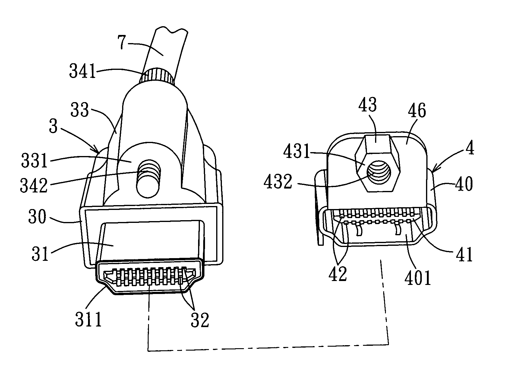
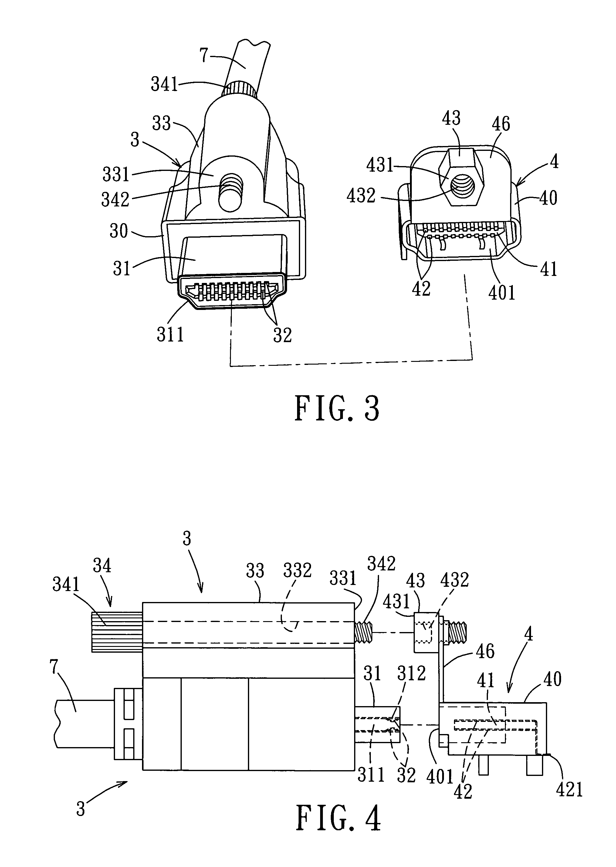
[0026]Referring to FIGS. 3 and 4, the first preferred embodiment of an electrical connector assembly according to the present invention is shown to include a first electrical connector 3, a second electrical connector 4, and a fastening unit.

[0027]The first electrical connector 3 includes a first housing 30 that has an insertion end portion 31 extending along a direction and formed with a receiving space 311 that is defined by an inner wall surface 312, and a set of conductive contacts 32 disposed in the receiving space 311 and mounted on the inner wall surface 312. In this embodiment, the conductive contacts 32 are coupled electrically to a cable 7.

[0028]The second electrical connector 4 includes a hollow second housing 40 that has an opening 401 and that permits extension of the insertion end portion 31 of the...


PUM


Abstract

An electrical connector assembly includes a first electrical connector having conductive contacts disposed in a receiving space in an insertion end portion of a first housing. A second electrical connector includes a terminal-mounting seat disposed in a hollow second housing and mounted with conductive terminals. When the insertion end portion of the first housing is inserted into the second housing, the terminal-mounting seat is received fittingly in the receiving space in the insertion end portion of the first housing, and the conductive terminals contact electrically and respectively the conductive contacts. A fastening unit prevents relative movement between the first and second housings so as to maintain electrical contact between the conductive contacts and the conductive terminals.

Description

BACKGROUND OF THE INVENTION[0001]1. Field of the Invention[0002]The invention relates to an electrical connector assembly, more particularly to an electrical connector assembly that includes a fastening unit for preventing relative movement between two connectors when the connectors are electrically interconnected.[0003]2. Description of the Related Art[0004]FIGS. 1 and 2 illustrate a conventional electrical connector assembly that can be used for signal transmission via an HDMI interface and that includes a first electrical connector 1 and a second electrical connector 2. The first electrical connector 1 includes a first housing 10 that has an insertion end portion 11 formed with a receiving space 14, and a set of conductive contacts 12 disposed in the receiving space 14 and connected electrically to another electrical connector (not shown) via a cable 13. The second electrical connector 2 includes a hollow second housing 20 having an opening 23, and a set of conductive terminals 2...

Claims


Application Information

Patent Timeline
Patent Type & Authority Patents(United States)
IPC IPC(8): H01R13/627
CPCH01R13/6215H01R13/6275
Inventor HUANG, GEORGE YING-LIANG
Owner HUANG GEORGE YING LIANG
Why Eureka
Try Eureka