Dynamic time to first print selection

a dynamic time and printhead technology, applied in the field of printing machines, can solve the problems of increasing the speed of printing machines and requiring longer times to reach lock, and achieve the effect of reducing the lock time of the printhead, fasting the time to first print, and fasting the overall printing tim

Active Publication Date: 2006-11-14
LEXMARK INT INC +1
View PDF4 Cites 15 Cited by
  • Summary
  • Abstract
  • Description
  • Claims
  • Application Information

AI Technical Summary

Benefits of technology

[0004]In accordance with this invention, short print jobs (normally one to ten or more pages depending on the timing of the actual printer, jobs of up to three or four pages in the embodiment disclosed in detail) are printed at a lower speed than the maximum speed that the printer could print such a job. This results in faster time to first print and potentially faster overall printing time because the printhead speed lock time is materially reduced.
[0005]By printing at an intermediate speed, the printer can be ready to begin imaging sooner (due to factors such as printhead speed lock) than it would be ready at max speed. When the job size is small, the time improvement from the quicker readiness can be greater than the time that is lost due to slower media movement. This results in the job being completed in less overall time.

Problems solved by technology

Moreover, some printers are operating at increasingly higher speeds, and such higher speeds require longer times to reach lock.

Method used


Image

  • Dynamic time to first print selection
  • Dynamic time to first print selection
  • Dynamic time to first print selection

Examples


Embodiment Construction

[0014]Printing System:

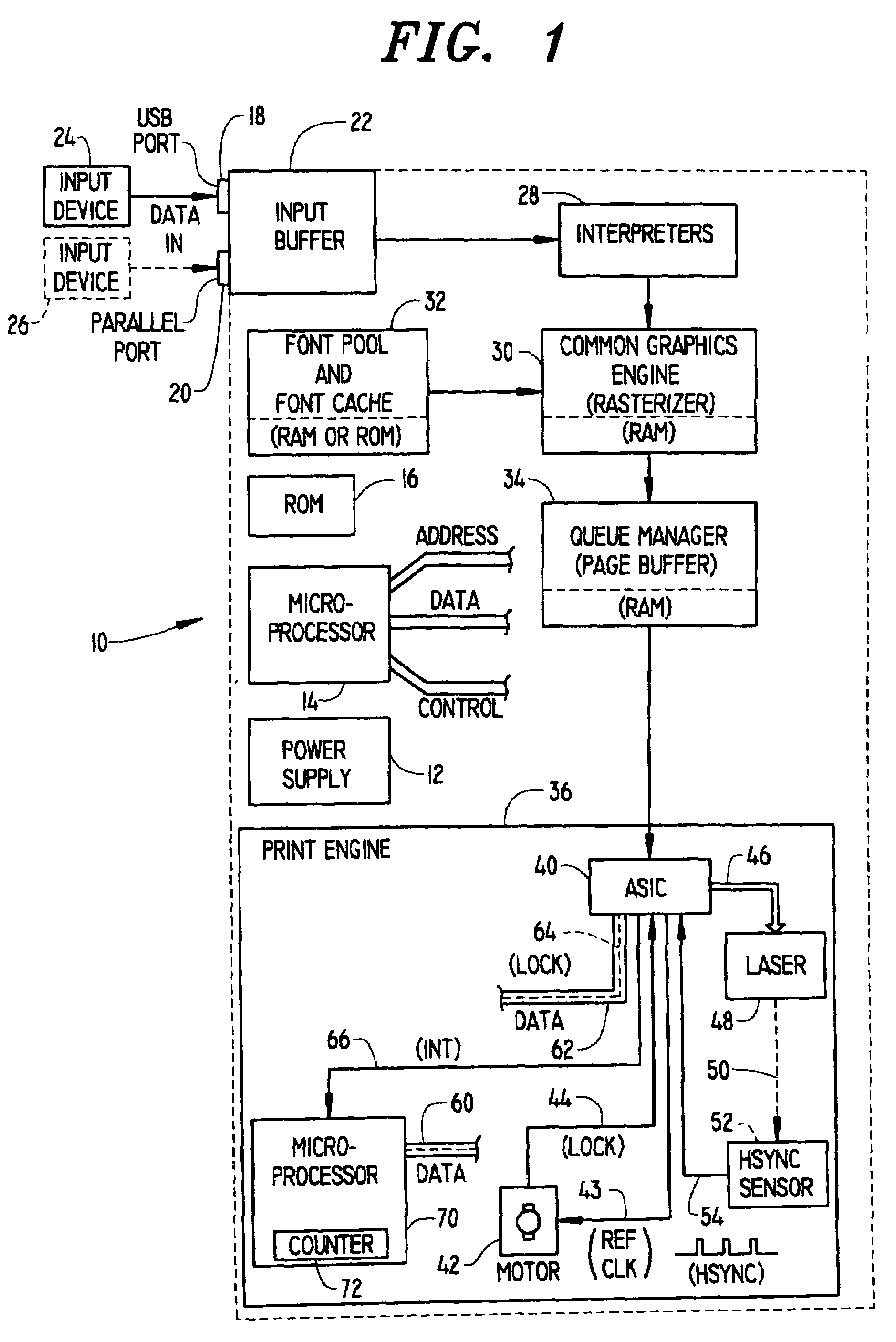
[0015]Referring now to the drawings, FIG. 1 shows a hardware block diagram of a laser printer generally designated by the reference numeral 10. Laser printer 10 will preferably contain certain relatively standard components such a DC power supply 12 which may have multiple outputs of different voltage levels, a microprocessor 14 having address lines, data lines and control and / or interrupt lines. Read Only Memory (ROM) 16, and Random Access Memory (RAM), are divided into several portions for performing several different functions.

[0016]Laser printer 10 will typically contain at least one network input (not shown), parallel input or USB port, or in many cases two or more types of input ports, so designated by the reference numeral 18 for the USB port and the reference numeral 20 for the parallel port. Each of these ports 18 and 20 would be connected to a corresponding input buffer, generally designated by the reference number 22 on FIG. 1. USB port 18 would typi...


PUM


Abstract

The number of pages of a print job received at printer (10) is determined (256). If the number of pages is low, printing is conducted at intermediate speed (262). If the number of pages is higher, printing is conducted at high speed (254). If the number of pages is not known, a default is selected (260). The default often will be to print at intermediate speed because most jobs are short. If high speed printing is in progress when a job is received, the next job is printed at high speed (254). Alternatively, a predetermined number of the first pages of a job may be printed at intermediate speed.

Description

TECHNICAL FIELD[0001]This invention relates to printers that require some tangible time between nonprinting status and actual marking on paper or other media. More specifically, this invention relates to improving the time to begin printing the first sheet of a job, which can also reduce the overall printing time for short print jobs.BACKGROUND OF THE INVENTION[0002]In laser printers of today, time to first print is often limited to the printhead lock time, which is the time period provided to permit the rotating printhead mirror to reach printing speed. Printhead lock is simply the stable operation of the laser printhead at a predetermined speed, and printhead lock time is the time period from start from inactive or partially active to assure printhead lock.[0003]Moreover, some printers are operating at increasingly higher speeds, and such higher speeds require longer times to reach lock. Conventional imaging devices print jobs of a predetermined kind, such as ordinary text printin...

Claims


Application Information

Patent Timeline
Patent Type & Authority Patents(United States)
IPC IPC(8): B41J2/435G03G15/00B41J11/42B41J13/00B41J29/38
CPCB41J11/425B41J13/0009B41J29/38
Inventor ABLE, DOUGLAS ANTHONYMICKAN, DAVID JOHNSCHOEDINGER, KEVIN DEAN
Owner LEXMARK INT INC
Why Eureka
Try Eureka