

System and method for cooling of a heated surgical instrument and/or surgical site and treating tissue
- Summary
- Abstract
- Description
- Claims
- Application Information
AI Technical Summary
Benefits of technology
Problems solved by technology
Method used
Image

Examples
Embodiment Construction
[0093]The invention and accompanying drawings will now be discussed in reference to the numerals provided therein so as to enable one skilled in the art to practice the present invention. The drawings and descriptions are exemplary of various aspects of the invention and are not intended to narrow the scope of the appended claims.
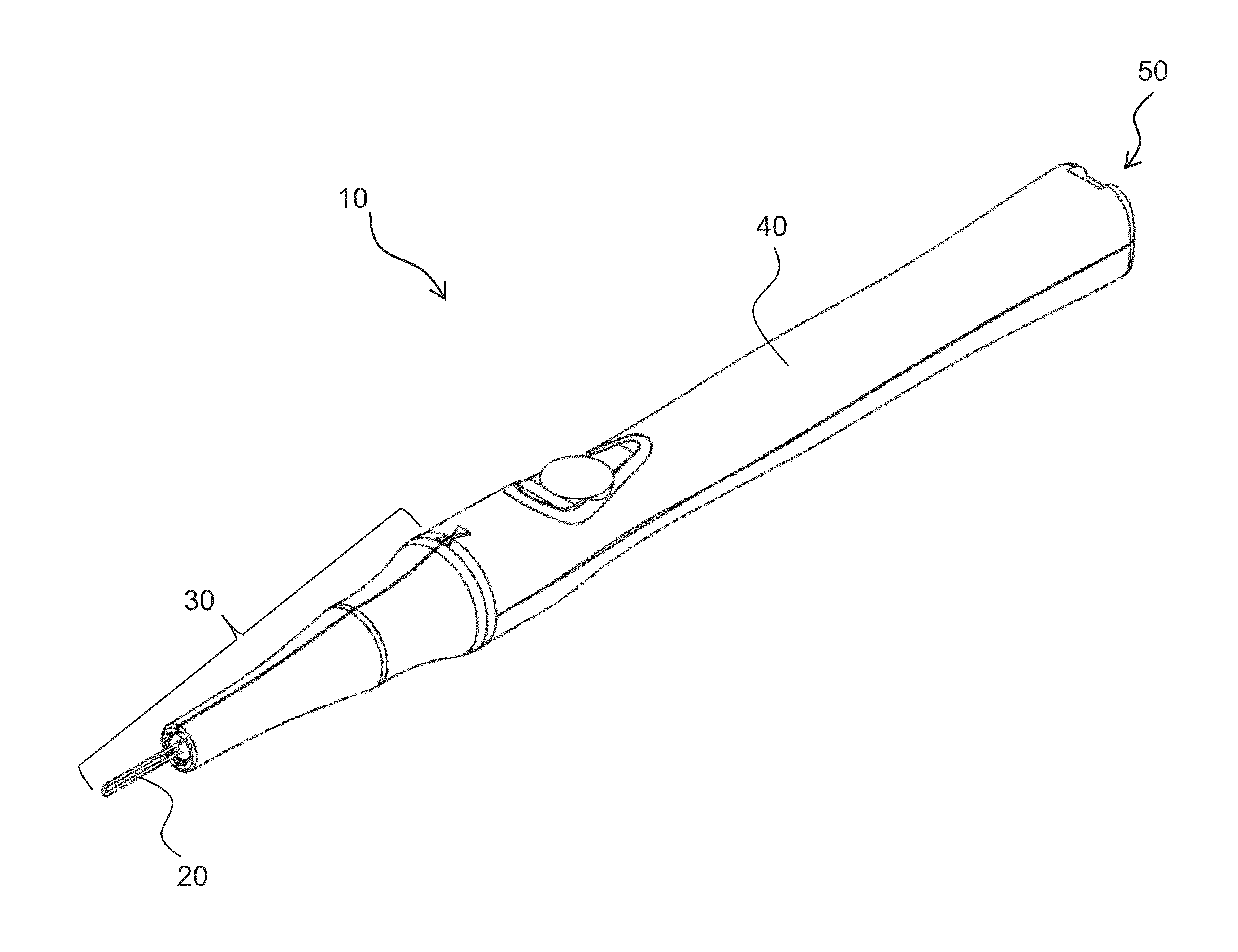
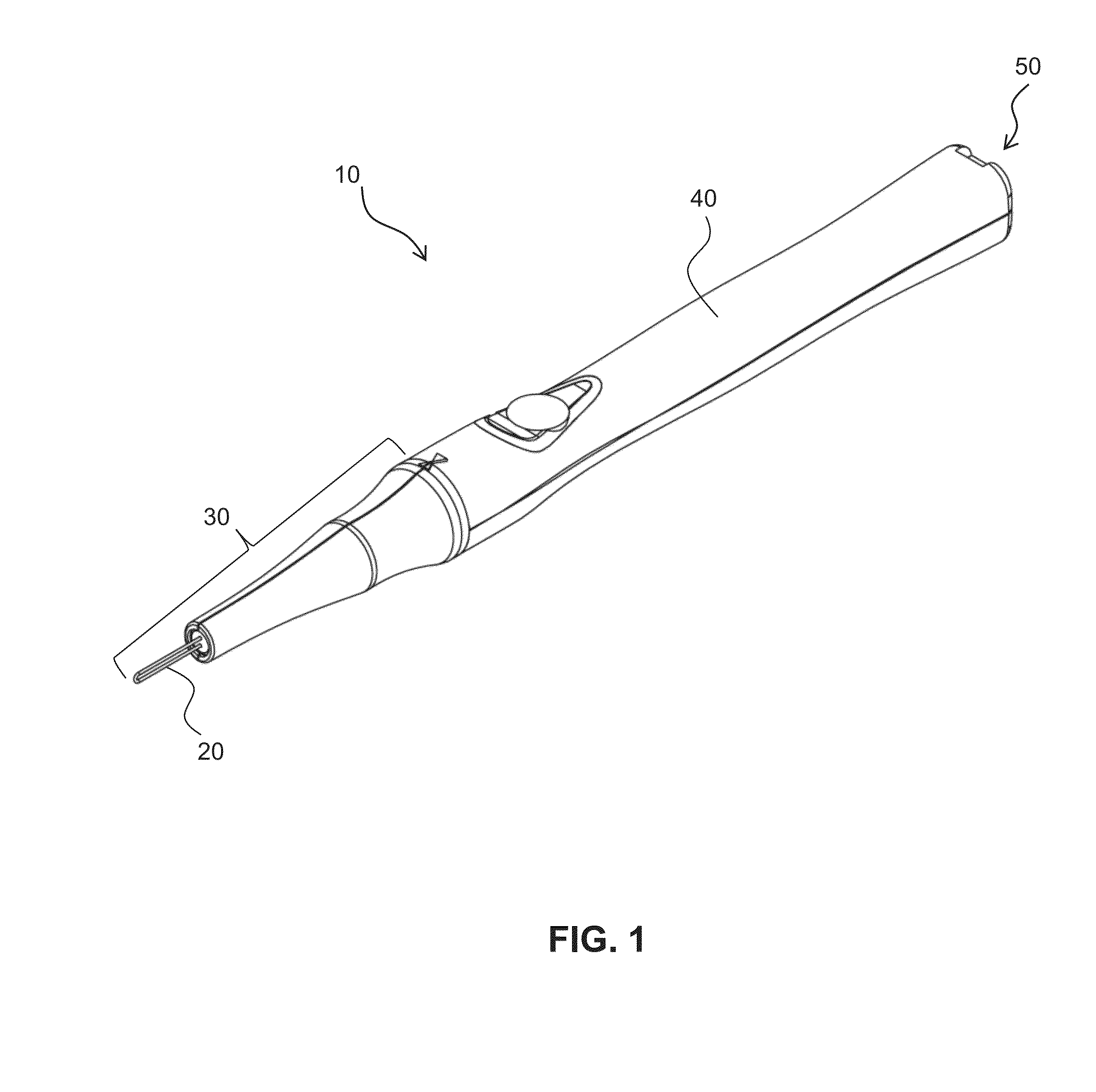
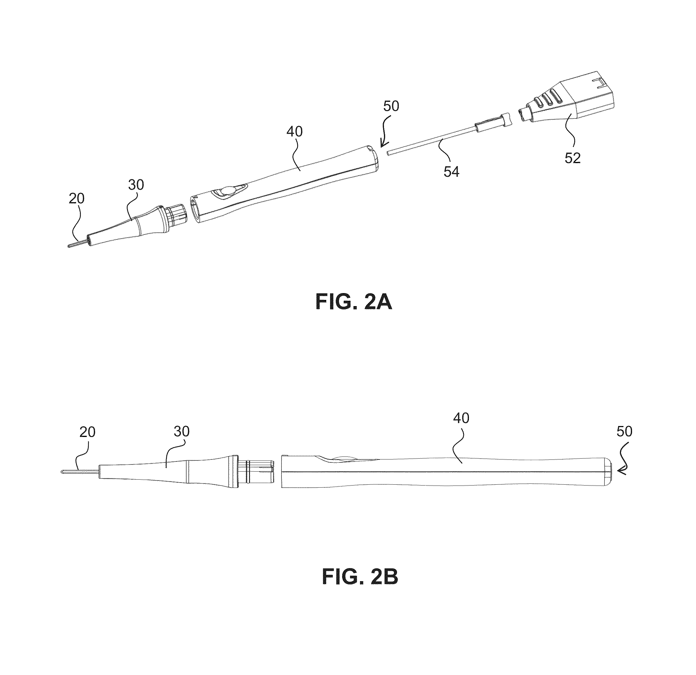
[0094]Turning now to FIG. 1, there is shown a perspective view of a surgical handpiece, generally indicated at 10, with a cooling system. The surgical handpiece includes an active thermal element 20 which may be formed as part of a tip 30. The tip 30 may be integrally formed with, attached and / or removable from a body 40, all or a portion of which may form a handle portion.
[0095]A surgical handpiece, such as handpiece 10, may be very important to a surgeon's effectiveness in surgery. This is particularly so with electrosurgery, whether using electrical energy, mechanical energy or thermal energy to cut and / or coagulate tissue and blood vessels. The more pre...
PUM
 Abstract
Description
Claims
Application Information