Screw and plastic part unit

a technology of screw and plastic part, applied in the direction of screws, threaded fasteners, washing machines, etc., can solve the problem of saving time and effort for the person using the guid

Inactive Publication Date: 2006-11-21
WEINSTEIN BURTON +1
View PDF15 Cites 12 Cited by
  • Summary
  • Abstract
  • Description
  • Claims
  • Application Information

AI Technical Summary

Benefits of technology

[0007]Other objects and advantage of the present invention will become more apparent upon reference to the following specification and annexed drawings in which:
[0008]FIGS. 1A and 1B are a top plan view and a perspective view respectively of a screw centering guide of plastic that is to be molded onto a screw;
[0009]FIGS. 2A, 2B and 2C are respective elevational perspective views of different types of screws that can be used with the invention;
[0010]FIG. 3A is an elevational perspective view partly broken away of the screw of FIG. 2A with the molded guide;
[0011]FIG. 3B is an elevational perspective view including a cross-sectional view of the guide used with the screw of FIG. 2B;
[0012]FIG. 3C is an elevational perspective view including a cross-sectional view of the guide used with the screw of FIG. 2C;

Problems solved by technology

This saves time and effort for the person using the guide.

Method used


Image

  • Screw and plastic part unit
  • Screw and plastic part unit
  • Screw and plastic part unit

Examples


Embodiment Construction

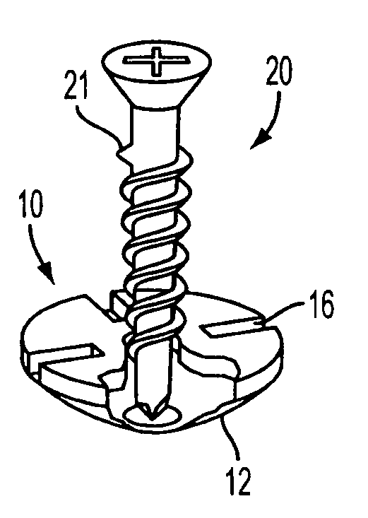
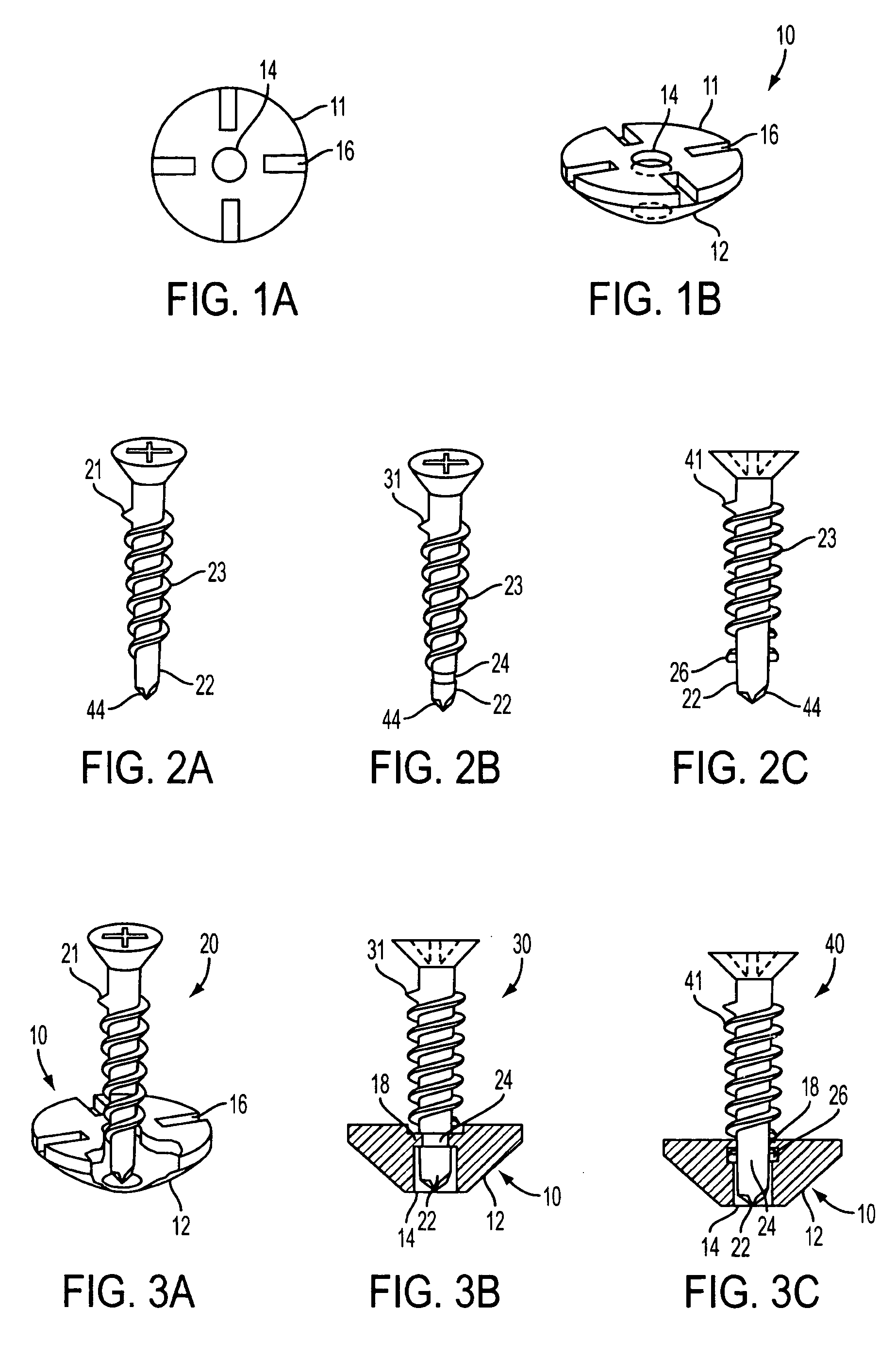
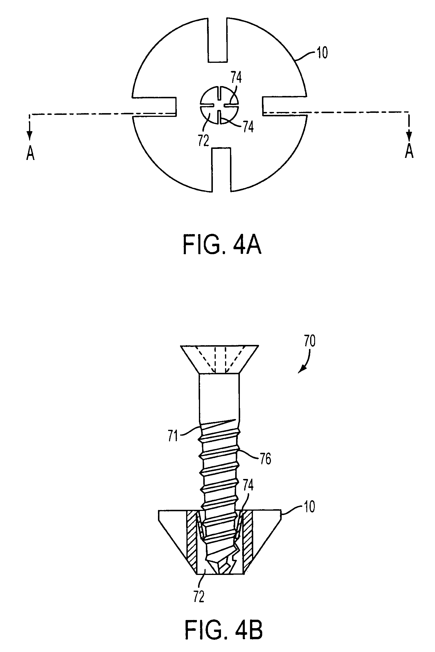
[0015]FIGS. 1A and 1B show one type of a plastic part 10 that is to be molded onto a screw such as one of the types shown in FIGS. 2A–2C. This is a plastic screw centering guide that has a generally circular top 11 and a tapered bottom 12 to be placed in the countersink of a member, such as a hinge leaf. The plastic guide has a through hole 14 for a screw to pass through and four cutouts 16 in pairs that are diametrically opposed. The cutouts 16 are generally rectangular and extend down into the guide body for a desired amount, for example from 20–30% of the height of the guide. The cutouts 16 facilitate splitting of the guide 10 as the screw is threaded into the workpiece. This operation is disclosed in the aforesaid patent. The guide 10 of FIGS. 1A–1B differs from that shown in the patent which has only two cutouts 16 diametrically spaced.

[0016]Screws 21, 31 and 41 are shown in FIGS. 2A, 2B and 2C and are so-called drill point type screws. While the screws are shown as being of th...


PUM


Abstract

A screw-plastic part unit in which the plastic part can be a guide having a tapered bottom end for fitting into a countersink to center the tip end of the screw in the countersink and also can have at least one cut-out portion at its top end to facilitate fracturing of the guide as the screw is threaded into a base member. In one embodiment the screw has a thread between its head and tip end which extends to near the tip end leaving a clear area between the thread end tip end and the part of plastic material molded around the screw clear area in which there can be a circumferential groove or rib into or over which the plastic part is molded to better hold the part to the screw. In another embodiment fins extend into the part hole to hold the screw by an interference type fit.

Description

PRIORITY CLAIM[0001]This application claims the benefit of priority under 35 U.S.C. § 119(e) from U.S. Provisional application Ser. No. 60 / 529,812, filed Dec. 16, 2003, entitled “SCREW ONTO WHICH A PART IS MOLDED”, the disclosure of which is incorporated by reference as if set forth fully herein.FIELD OF THE INVENTION[0002]The invention relates to a unit of a screw and a plastic part, such as a guide to position placement of the screw at a precise location.BACKGROUND OF THE INVENTION[0003]U.S. Pat. No. 6,602,027 granted on Aug. 26, 2003, the disclosure of which is incorporated in its entirety herein by reference, shows various types of screw centering guides of frangible plastic material in which a screw is placed. The guide has a tapered bottom end to be used to accurately position the screw in the center of a hole of a countersink, for example, one located on a hinge leaf. When the screw is threaded into the underlying workpiece to which the hinge leaf is being fastened, typically...

Claims


Application Information

Patent Timeline
Patent Type & Authority Patents(United States)
IPC IPC(8): F16B23/00F16B35/02F16B43/00F16B43/02F16B1/00F16B41/00
CPCF16B29/00F16B41/002F16B41/005F16B43/00F16B2001/0092F16B2200/99
Inventor WEINSTEIN, BURTONDEATON, RICHARD H.
Owner WEINSTEIN BURTON
Why Eureka
Try Eureka