
Damped armrest

a technology for lowering armrests and armrests, which is applied in the direction of vehicle components, chairs, vehicles, etc., can solve the problems of uncontrollable pivotally mounted armrests falling from the raised position, armrests may be sufficiently worn, and the inability to adjust the height of the armrest, etc., to achieve simple and inexpensive dampers, easy assembly and installation, and easy removal

Active Publication Date: 2006-11-28
ILLINOIS TOOL WORKS INC
View PDF9 Cites 15 Cited by
  • Summary
  • Abstract
  • Description
  • Claims
  • Application Information

AI Technical Summary

Benefits of technology

[0011]An advantage of the present invention is providing a damping structure to control the movement of an armrest between raised and lowered positions so that the armrest moves steady and smooth throughout the range of movement.
[0012]Another advantage of the present invention is providing a damped armrest that is easily assembled and installed.
[0013]A further advantage of the present invention is providing a damper mechanism for an armrest of a vehicle seat, that allows the armrest to be easily and conveniently removed from the supporting structure of the seat and reattached to the supporting structure of the seat.
[0014]A still further advantage of the present invention is providing a simple and inexpensive damper for a vehicle armrest that operates smoothly and effectively for an extended period of time.
[0015]Other features and advantages of the invention will become apparent to those skilled in the art upon review of the following detailed description, claims and drawings in which like numerals are used to designate like features.

Problems solved by technology

However, ingress and egress around fixed armrests can be difficult.
An uncontrolled pivotally mounted armrest can fall from the raised position, suddenly and unexpectedly.
After a period of use, the armrest may be sufficiently worn that only a slight bump or jar of the seat or armrest can cause the armrest to fall from the raised to the lowered position.
This can be inconvenient for elderly people or people with physical infirmities that create difficulties in entering and leaving the seat.
Unintended lowering of the armrest also can present difficulties for adults attempting to position children in the seat, or in a child seat secured to the vehicle seat.

Method used


Image

  • Damped armrest
  • Damped armrest
  • Damped armrest

Examples


Embodiment Construction

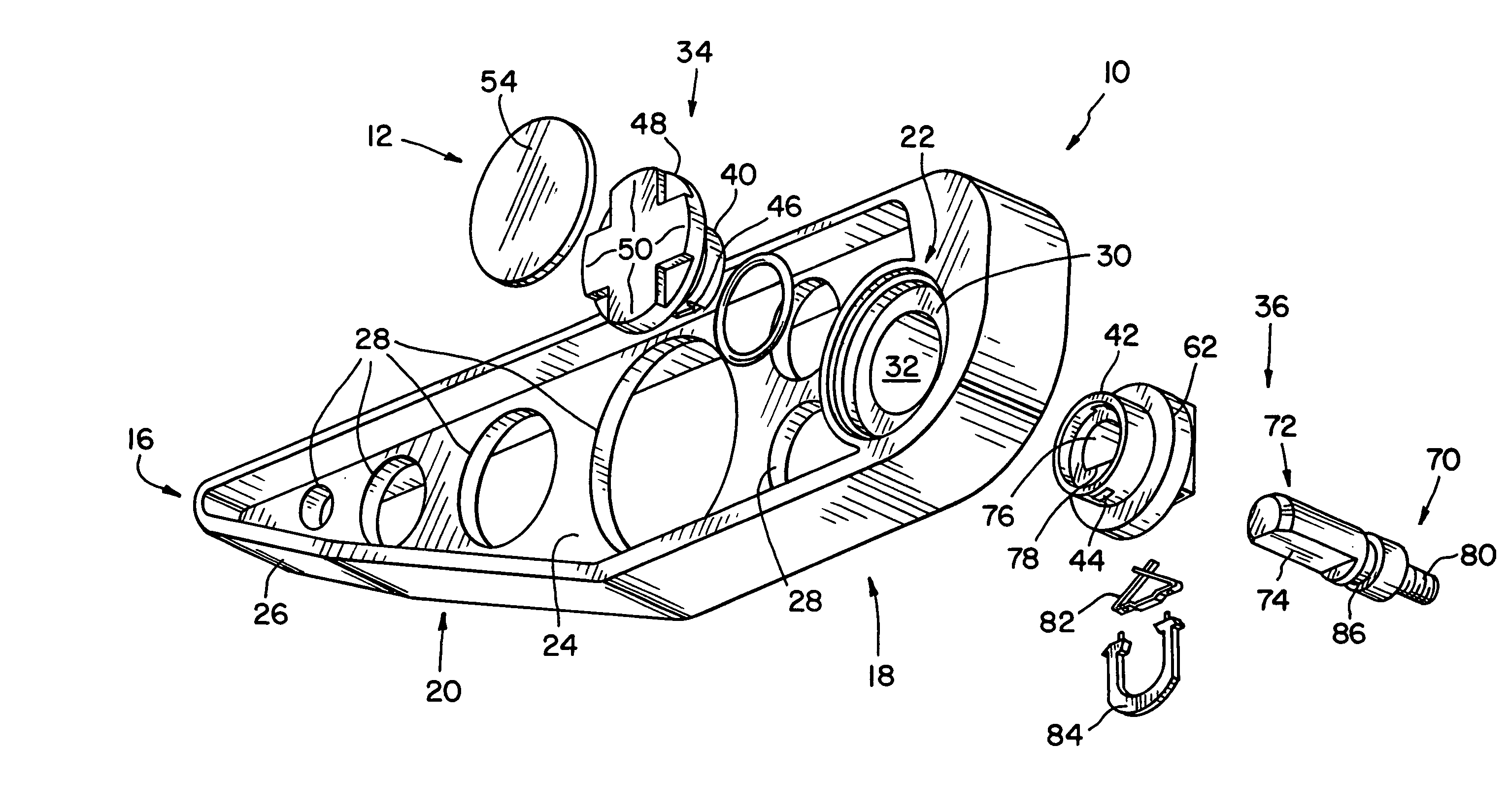
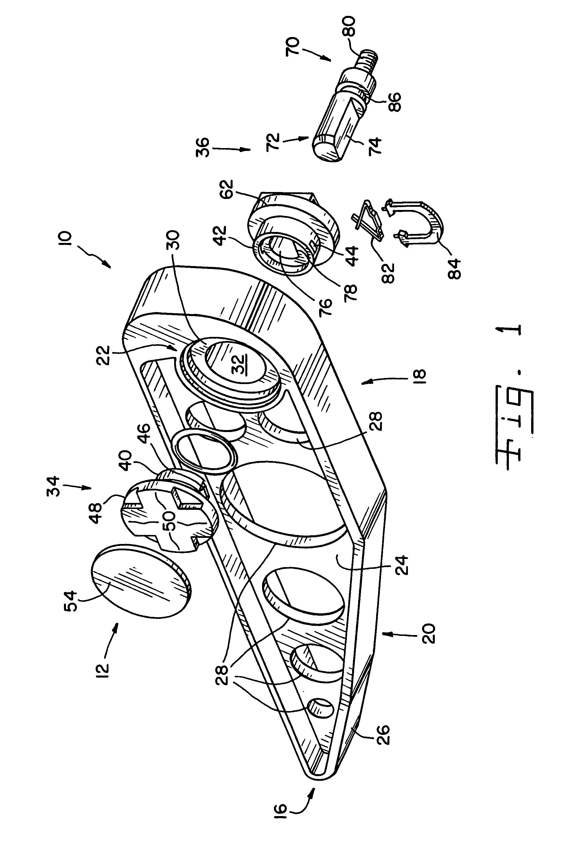
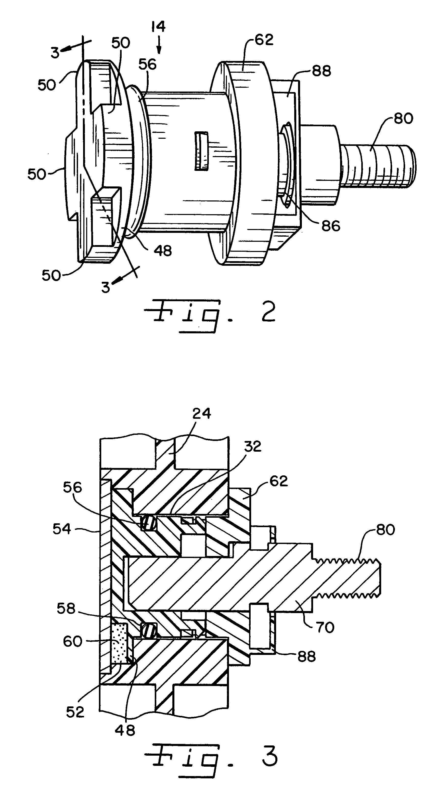
[0020]Referring now more specifically to the drawings and to FIG. 1 in particular, a vehicle armrest 10 is shown having an armrest damper 12 in accordance with the present invention as part of a mandrel assembly 14 defining the pivotal axis of armrest 10. Those skilled in the art will understand readily that an external covering (not shown) will be provided on armrest 10, and may include a sprayed vinyl foam that is skinned over, or other padding materials covered with a sleeve of fabric, leather or the like.

[0021]Armrest 10 includes a frame 16 of plastic or the like. Frame 16 generally defines the size, shape and general configuration of the completed armrest. The exact size, shape and general configuration of frame 16 will vary, depending upon the size, shape and configuration of the seat (not shown) on which armrest 10 is installed. In the exemplary embodiment, frame 16 has a substantially rectangular rearward portion 18 and a tapered nose portion 20 extending forwardly therefrom...


PUM


Abstract

A damped armrest including an armrest frame defining a bore and a fixed mandrel defining an axis about which the frame rotates. A reservoir is formed by the bore and the mandrel. Vanes on the mandrel project into the reservoir. The reservoir is filled with damping media for controlling rotation of the frame about the mandrel.

Description

CROSS-REFERENCE TO RELATED APPLICATIONS[0001]This United States Patent Application claims the benefits of U.S. Provisional Application Ser. No. 60 / 493,597, filed Aug. 8, 2003.FIELD OF THE INVENTION[0002]The present invention relates generally to movable vehicle armrests and, more specifically, the invention pertains to damping mechanisms for controlling movement of the armrest.BACKGROUND OF THE INVENTION[0003]Seating arrangements in vehicles often provide individual seats for the driver and at least some passengers. In vans, trucks, motor homes and the like, passengers and drivers may access the individualized seat provided for them by sliding into the seat from a side thereof. Egress from the seat may be achieved in the same manner.[0004]For comfort, relaxation and a feeling of security, it is known to provide armrests along the sides of the individualized seats. In some seat designs, the armrests are formed integrally with the seat bottom and / or seat back. However, ingress and egr...

Claims


Application Information

Patent Timeline
Patent Type & Authority Patents(United States)
IPC IPC(8): A47C7/54B60N2/75
CPCB60N2/4606B60N2/753
Inventor HANN, MARK S.
Owner ILLINOIS TOOL WORKS INC
Learn More