Label ledge for injection molded containers

a technology of injection molding and label ledges, which is applied in the field of improved labeling for food and drink containers, can solve the problems of increasing the cost of each container, affecting the quality of the container, so as to reduce the cycle time and minimize the associated costs

Inactive Publication Date: 2006-11-28
IML BY IDESIGN
View PDF20 Cites 12 Cited by
  • Summary
  • Abstract
  • Description
  • Claims
  • Application Information

AI Technical Summary

Benefits of technology

[0013]It is an object of an exemplary form of the present invention to provide an in mold label that can be used in in mold labeling injection molding processes and prevents or minimizes label displacement during resin flow through the mold.

Problems solved by technology

Labels that are glued or otherwise applied to the container after manufacturing often peel or wash off.
This is undesirable in a product subjected to repeated squeezing, such as drinking cups and container tops.
Moreover, when these containers are subjected to extreme temperatures, such as when they contain ice cream, the extreme temperatures often cause a full fracture to develop along the latent fracture line.
However, using the low melt resin increases the cost of each container because of the increased processing time.
In addition, the resulting containers are often heavier or have thicker walls than necessary for the product that the container is designed to hold.
Some manufacturers use high melt resin for the bulk of their products, but must also keep low melt resin available to produce in mold labeled products which cannot be made out of high melt resin, solely because the of the latent fractures created by the traditional in mold labels.
Often the injection molding process drags ink from the edge cuts of the in mold label into the resin used to form the container, causing undesirable streaks in the resulting container.
Although the resulting ink streaks are harmless, they are commercially unacceptable.
As a result, a portion of each batch of containers must be discarded because their appearance is unacceptable.
This streaking occurs when both low melt and high melt resin are used, and cannot be overcome by selection of an appropriate resin type.
Problems arise when the corners or radiused portions of the container are adjacent the area where the in mold label is to be placed.
The flow of resin displaces the label away from the cavity wall and flows around both sides of the label, causing scrap.
This leads to the wasting of large amounts of molding material, which correlate to increased manufacturing costs.
Furthermore, the labels are not currently placed on elevated planes of containers.
However, the attempts to place labels on the container lids encounter the same challenges as seen with the labels placed around the container body: The lids have corners or radiused portions adjacent the area where the in mold label is to be placed.
Thus, a need exists for a label that can be applied during the injection molding process that does not permit displacement of a label during the flow of resin through the mold.

Method used


Image

  • Label ledge for injection molded containers
  • Label ledge for injection molded containers
  • Label ledge for injection molded containers

Examples


Embodiment Construction

[0050]It should be understood that positional references in this specification, including but not limited to above, below, right, left, vertical, and horizontal, are used solely for the purpose of identifying the portion of a particular illustration to which reference is made, and do not indicate an absolute position.

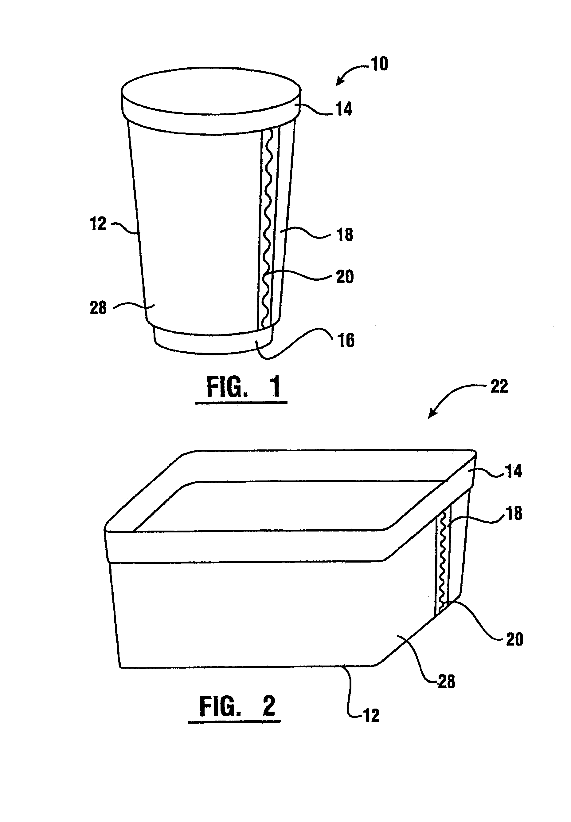
[0051]Referring now to FIG. 1, there is shown a cup formed using an injection mold. The cup is generally referred to by reference numeral 10. Cups 10 of this nature are often provided to customers buying beverages at carry-out restaurants, sports events, amusement parks and other similar events. Cups 10 are often taken home by customers, and reused for casual dining, providing an opportunity for others to view whatever design is on the cup 10.

[0052]The exemplary cup 10 bears a label 12, which wraps around the cup 10, and was applied in mold. As illustrated in FIG. 1, label 12 contains a joined registration area 18. Roughly in the center of the joined registration area 1...


PUM

PropertyMeasurementUnit
perimeteraaaaaaaaaa
thicknessaaaaaaaaaa
shapeaaaaaaaaaa

Abstract

An improved in mold label for use in labeling products made by injection, or other, molding technologies has a zig-zag shaped edge cut contained in a registration area which contains ink that matches the product resin. At least one ledge is formed in a cavity wall of the mold proximate the position intended for receipt of an in mold label. The ledge protects the leading edge of the in mold label from the flow of resin through the cavity walls of the mold. Because the label leading edge is protected, the resin flows over the label and pins the label to the cavity wall of the mold, creating a container with the label formed on the container wall. Alternatively, a container lid is provided with a ledge to facilitate skirting and label placement on the pan area of the lid. These features both enhance the structural integrity and the uniform unblemished appearance of the finished molded container. Because of the enhanced structural integrity, high melt resin may be used to create the container, reducing the cycle time, and thus the cost of the product. The lack of blemishes in the finished container reduces manufacturing waste.

Description

CROSS REFERENCE TO RELATED APPLICATIONS[0001]This application claims benefit from previously filed provisional application Ser. No. 60 / 342,730, filed Dec. 21, 2001, and non-provisional application Ser. No. (not yet assigned), filed Dec. 20, 2002, which is incorporated herein by reference.BACKGROUND OF THE INVENTION[0002]This invention relates generally to an improved label for food and drink containers made using an injection molding process. Specifically, this invention relates to a label ledge which supports a label that is applied to the product packaging during the injection molding process which results in a stronger, more attractive container than those made using in mold labeling.[0003]Many plastic products are made using either injection or blow mold technology. Products that are made by injection molding are typically made using either a low melt resin or a high melt resin. When a lightweight or thin walled container is desired, it is generally more cost effective to make i...

Claims


Application Information

Patent Timeline
Patent Type & Authority Patents(United States)
IPC IPC(8): B29C45/14B29C49/02B29C49/06B29C49/24B65D23/08B65D25/20B65D51/24
CPCB29C45/14B29C49/24B65D25/205B65D51/245B29C45/14475B29C49/02B29C49/06B29C2045/14909B29C2045/14918B29C2045/14934B29C2049/2412B29C2049/242B29C2049/2449B29C2049/2493B29L2031/712B29C2049/2414B29C2049/24304B29C2949/0715
Inventor GRAHAM, BRIAN K.
Owner IML BY IDESIGN
Why Eureka
Try Eureka