Wire grommet

a wire grommet and wire technology, applied in the direction of insulating bodies, cables, insulated conductors, etc., can solve the problem that holes often remain unused

Inactive Publication Date: 2006-11-28
NICOLET PLASTIQUE
View PDF9 Cites 30 Cited by
  • Summary
  • Abstract
  • Description
  • Claims
  • Application Information

AI Technical Summary

Problems solved by technology

However, in practice, these holes often remain unused.

Method used


Image

  • Wire grommet
  • Wire grommet
  • Wire grommet

Examples


Embodiment Construction

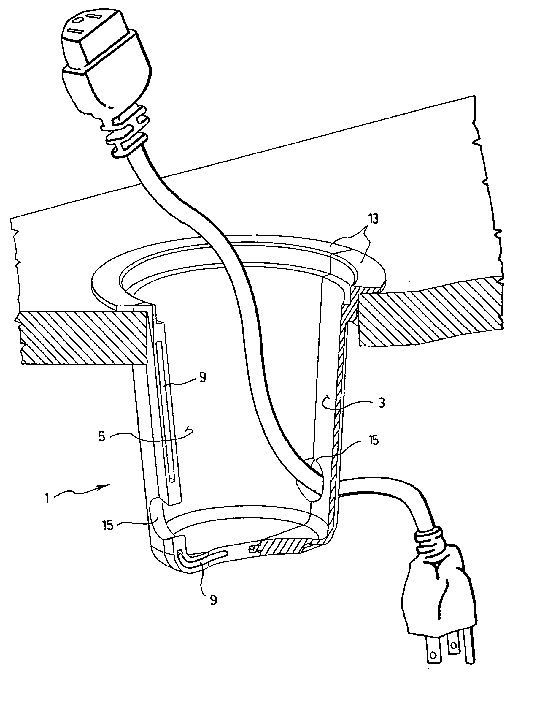
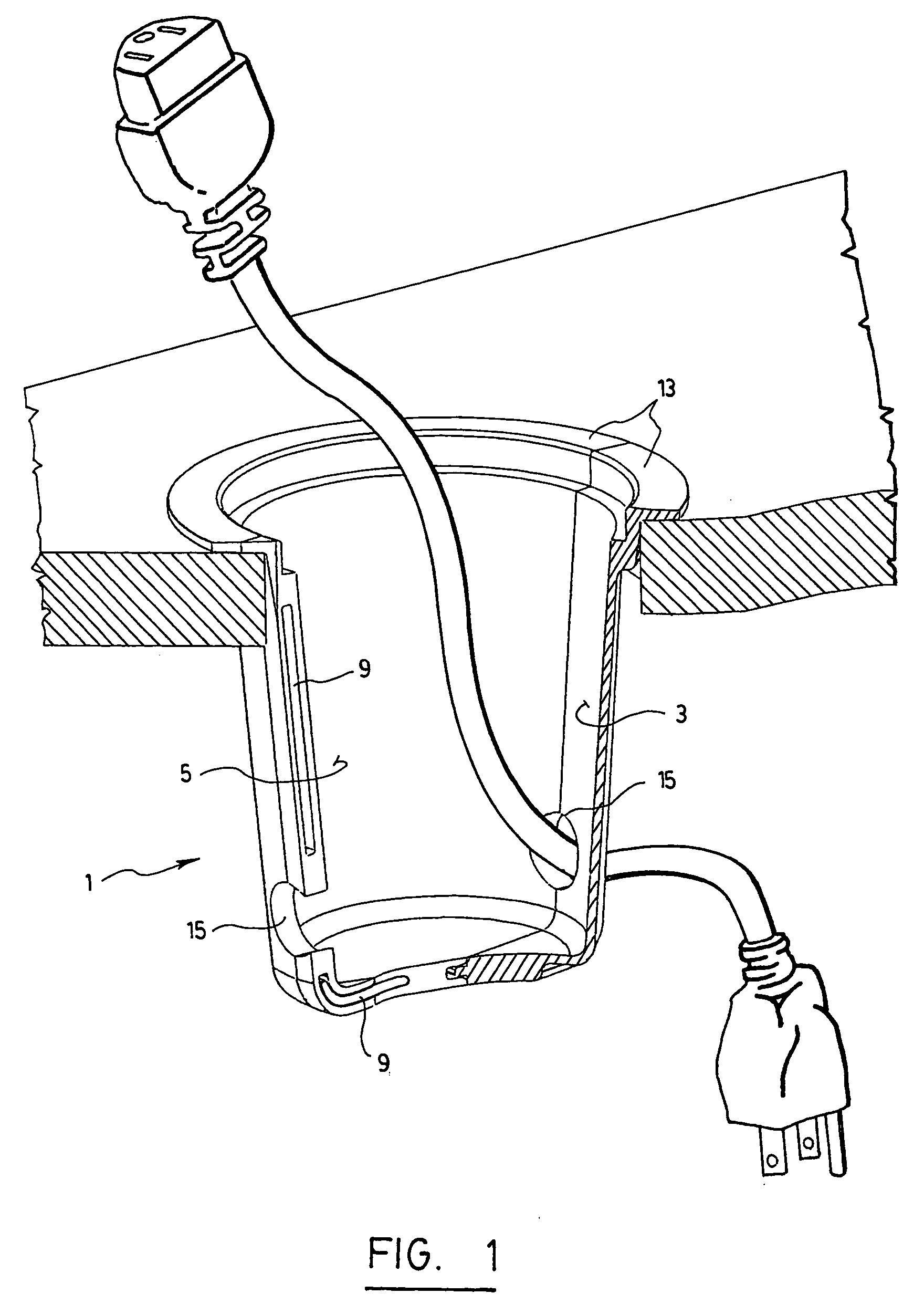
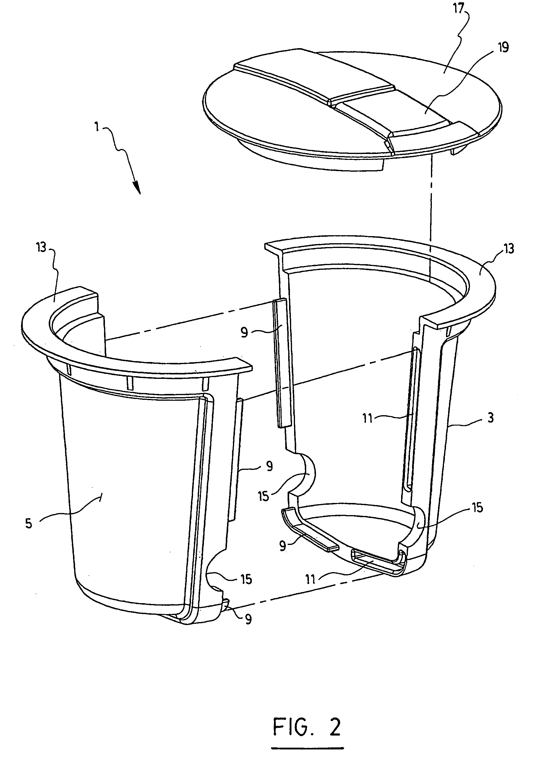
[0011]The wire grommet 1 according to the preferred embodiment of the invention shown in the accompanying drawings, are made of two identical elements 3 and 5 which form an open container when they are assembled together. In order to proceed to this assembly, tongues 9 and grooves 11 are provided into the lateral edges of the elements 3 and 5 in order to assemble and disassemble the same at will. Tongues and grooves may also be provided on the bottom of each of the elements so as to complete their assembly.

[0012]Each element 3, 5 comprises an upper rim 13 which projects outwardly in order to fit onto the edges of the hole of the panel into which the wire grommet is intended to be positioned (see FIG. 1). The upper rim 13 may also mask the imperfections that may exist all around the hole, especially if this one is made into the panel by a user.

[0013]Each of the elements 3, 5 also comprises at least one recess 15 on one of its edges preferably close to its bottom in order to, once bot...


PUM


Abstract

Disclosed is a wire grommet intended to be positioned in a hole made into a surface of a panel or plate. The grommet is made of two identical elements having adjacent edges provided with tongues and grooves allowing them to be assembled to form an open container with a size and shape adapted to allow it to be inserted into the hole and be maintained within the same. The elements also have recesses in their edges which altogether form at least one opening through which one or more wires may pass when the elements are assembled. Advantageously, the wire grommet also comprises a closing cap fittable into both elements when the elements are assembled, in order to close the container formed by the same.

Description

FIELD OF THE INVENTION[0001]The present invention relates to a wire grommet intended to be positioned in a hole made in a surface of a panel or plate, especially a table or a desk. This wire grommet is devised to let one or more wires pass through it while also acting as a pen holder or a storing space.TECHNOLOGICAL BACKGROUND[0002]In the field of furniture, especially desks, tables or shelves, it is of common practice to provide holes in the surface of plates or panels so as to pass wires necessary to connect the electrical or electronic equipment. However, in practice, these holes often remain unused.SUMMARY OF THE INVENTION[0003]The object of the present invention is to provide a piece intended to be inserted into a hole made into a plate or a panel in order to, on the one hand, always permit to this hole to act as a wire grommet and, on the other hand, act as a pen holder or form a storing space.[0004]More specifically, the invention is directed to a wire grommet intended to be ...

Claims


Application Information

Patent Timeline
Patent Type & Authority Patents(United States)
IPC IPC(8): H02G3/18
CPCA47B21/06Y10T16/05Y10T16/063A47B2200/0082
Inventor CLOUTIER, MICHEL
Owner NICOLET PLASTIQUE
Why Eureka
Try Eureka