Intervertebral implants

a technology of intervertebral implants and implants, which is applied in the field of biocompatible implants, can solve the problems of limiting the size of implants which can be formed from bone, the specific size of implants required for surgical procedures will not be known to any certainty, and the difficulty in adapting implants to meet the size requirements

Inactive Publication Date: 2010-02-16
WARSAW ORTHOPEDIC INC
View PDF291 Cites 73 Cited by
  • Summary
  • Abstract
  • Description
  • Claims
  • Application Information

AI Technical Summary

Problems solved by technology

One problem associated with known implants is the difficulty in adapting an implant to meet the size requirements of a particular intervertebral receiving bed.
For example, because anatomically all patients are different, the specific size of implant required for a surgical procedure will not be known to any certainty until a surgeon has prepared the intervertebral space for implantation.
Another problem associated with known implants constricted from bone is that the anatomical limitations of donor bone limit the size of the implant which can be formed from bone.
As a result, bone having satisfactory strength characteristics may not be available for use as an implant because of size limitations.
Finally, yet another problem associated with known implants is their inability to accurately maintain the natural lordoses of the spine.
Because of the irregular shape of the vertebral endplates, wedge-shaped implants and cylindrical dowels are incapable of supporting adjacent vertebrae in their natural orientation without substantially altering the shape of the vertebral endplate(s).

Method used


Image

  • Intervertebral implants
  • Intervertebral implants
  • Intervertebral implants

Examples


Embodiment Construction

[0047]Preferred embodiments of the presently disclosed intervertebral implant and implant extender will now be described in detail with reference to the drawings in which like reference numerals designate identical or corresponding elements in each of the several views.

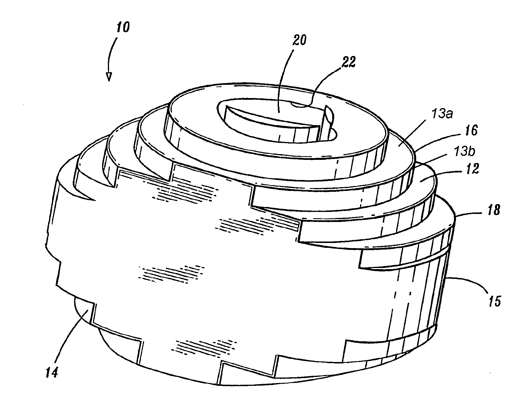
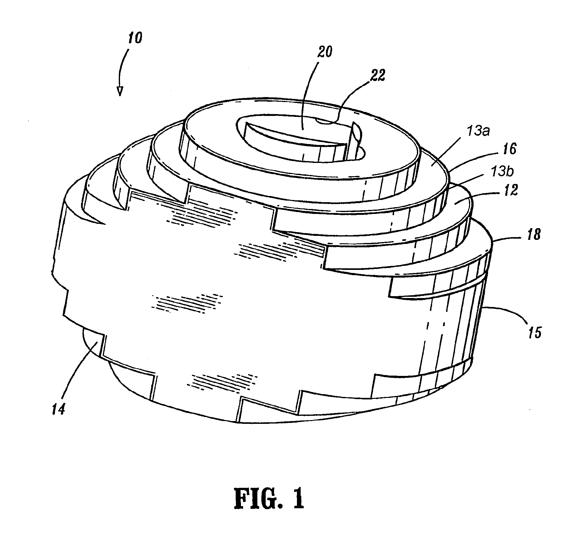
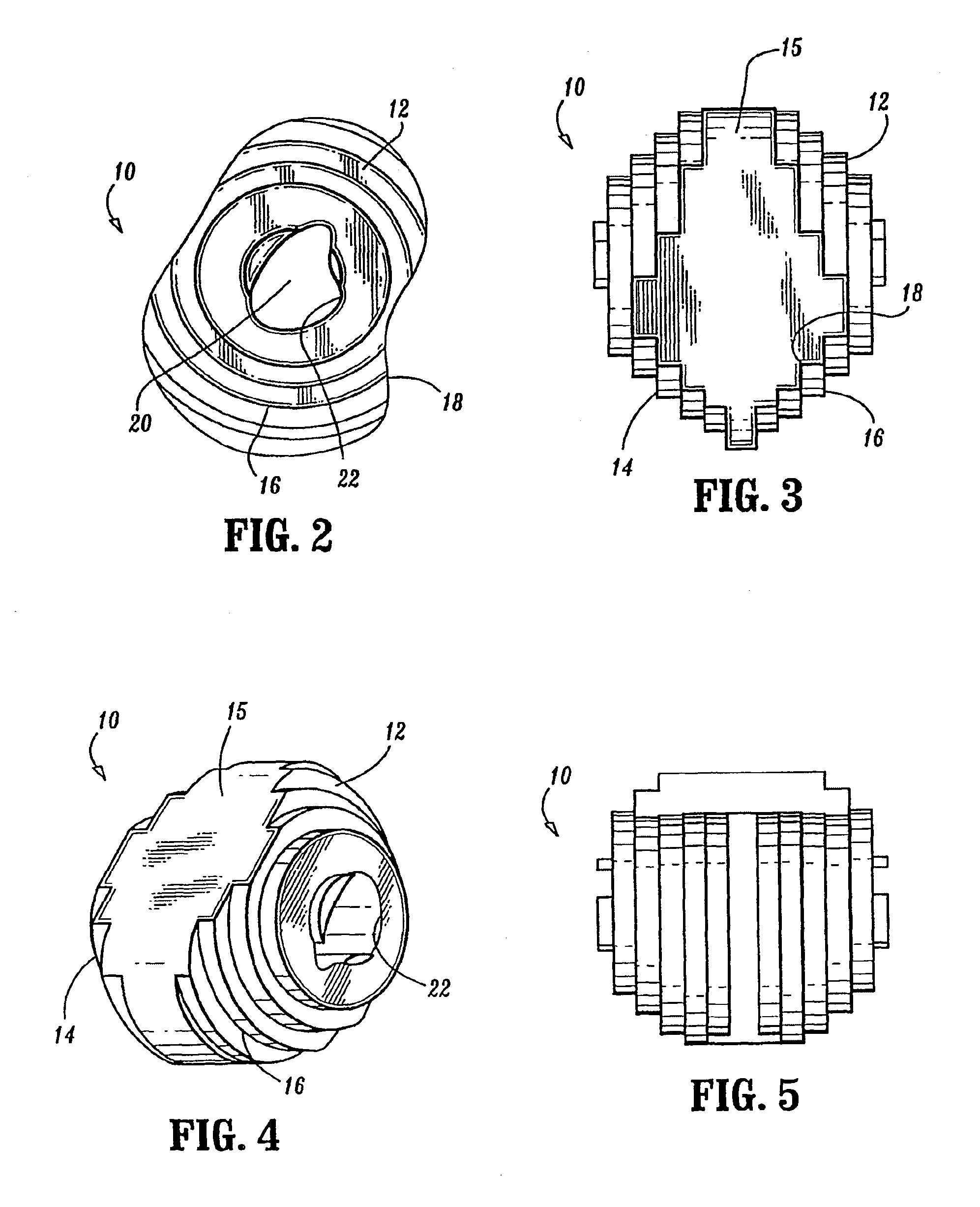
[0048]FIGS. 1-5 illustrate a preferred embodiment of the presently disclosed intervertebral implant shown generally as 10. Briefly, implant 10 includes an upper surface 12, a lower surface 14 and a sidewall 15 positioned between the upper and lower surfaces. Upper and lower surfaces 12 and 14 each include a series of circular steps 16 which move upwardly from the outer periphery 18 of implant 10 to the center 20 of implant 10. The steps 16 include a first plane 13a and a second plane 13b. The first plane 13a is defined by the crest portion of the curvilinear projection or step 16. As shown, the plane 13a may be generally flat. In some embodiments, the first plane 13a and second plane 13b may make a tapered configurati...


PUM


Abstract

A multipart intervertebral implant is provided which includes an implant portion and an implant extender portion. The implant portion and the implant extender portion can be fastened together using any known fastening means including pins, interlocking structure (e.g., dovetail, tongue and groove, etc.), adhesives, etc. The size of the implant extender portion can be selected during a surgical procedure to provide an implant suitable for a particular intervertebral receiving bed. An intervertebral implant is also provided which may be formed from a multiplicity of implant sections which are fastened together to provide an implant having a desired length. Implants having surface configurations which more closely correspond to the configuration of vertebral endplates are also provided.

Description

[0001]This application claims priority as a divisional application from and incorporates by reference U.S. Utility application Ser. No. 09 / 754,038, filed Jan. 2, 2001, now abandoned, which claims priority from U.S. Provisional Application Ser. No. 60 / 173,973, filed Dec. 30, 1999.BACKGROUND[0002]1. Technical Field[0003]The present disclosure relates generally to biocompatible implants and, more particularly, to intervertebral implants suitable for implantation into the lumbar, thoracic and / or cervical regions of the spine during a spinal fusion procedure.[0004]2. Background of Related Art[0005]Intervertebral implants for fusing together adjacent vertebrae of a spinal column are well known in the art. Such implants are formed in a variety of different shapes and sizes and are configured for insertion into receiving beds formed in the lumbar, thoracic and cervical regions of the spine. The implants may be formed from a variety of different biologically compatible materials including ce...

Claims


Application Information

Patent Timeline
Patent Type & Authority Patents(United States)
IPC IPC(8): A61F2/44A61F2/00A61F2/28A61F2/30A61F2/46
CPCA61F2/4455A61F2/28A61F2310/00359A61F2/442A61F2/4611A61F2002/2817A61F2002/2835A61F2002/2839A61F2002/30112A61F2002/30118A61F2002/30156A61F2002/30207A61F2002/3023A61F2002/30233A61F2002/30289A61F2002/30291A61F2002/30324A61F2002/30387A61F2002/30459A61F2002/30492A61F2002/30599A61F2002/30604A61F2002/30772A61F2002/30789A61F2002/30827A61F2002/3085A61F2002/30874A61F2002/4475A61F2220/0025A61F2220/0066A61F2230/0004A61F2230/0006A61F2230/0023A61F2230/0067A61F2230/0069A61F2230/0091A61F2250/0036A61F2250/0063A61F2310/00131A61F2310/00179A61F2/30965A61F2002/30593A61F2002/30873
Inventor ALFARO, ARTHUR A.SHIMP, LAWRENCE A.RUSSELL, JAMES L.BOYLE, JOHN W.MARTZ, ERIK O.ROSENTHAL, DANIEL E.MORRIS, JOHN W.
Owner WARSAW ORTHOPEDIC INC
Why Eureka
Try Eureka