Cursor locator for multi-monitor systems

a multi-monitor, cursor technology, applied in the field of computer systems, can solve the problems of large screen area, high price, and large screen area of monitors, and achieve the effect of reducing the number of graphics cards that may be combined, and reducing the number of screens

Active Publication Date: 2006-11-28
NVIDIA CORP
View PDF12 Cites 31 Cited by
  • Summary
  • Abstract
  • Description
  • Claims
  • Application Information

AI Technical Summary

Problems solved by technology

However, monitors with larger screen areas are expensive, and the price increase is typically disproportionate with the increase in screen area.
The number of graphics cards that may be combined is typically limited by the number of slots available for expansion, such as Peripheral Component Interconnect (PCI) slots or Accelerated Graphics Port (AGP) slots.
However, while multiple monitors may increase the visible screen area, the larger screen area may become more difficult to manage.
As an example, locating a relatively small cursor in a relatively large screen area may present a challenge.
Locating the cursor, which may be time-consuming on a single monitor, may become very time-consuming when the user has to hunt through a screen area spanning several monitors.
While tracking eyes may be fairly effective for a relatively small screen area of a single monitor, for the larger screen area of a multiple monitor, the distance from the tracking eyes may be too great to be effective.
Further, tracking images, such as the tracking eyes are typically displayed continuously and, therefore, take up precious screen real estate, which runs counter to the goal of expanding screen area.
However, in a multi-monitor system, the user may still have to scan multiple monitors to detect the visible cursor movements, which may result in an unacceptable delay.
This delay may lead to decreased productivity and, therefore, runs counter to increased productivity goals of a multi-monitor system.

Method used


Image

  • Cursor locator for multi-monitor systems
  • Cursor locator for multi-monitor systems
  • Cursor locator for multi-monitor systems

Examples


Embodiment Construction

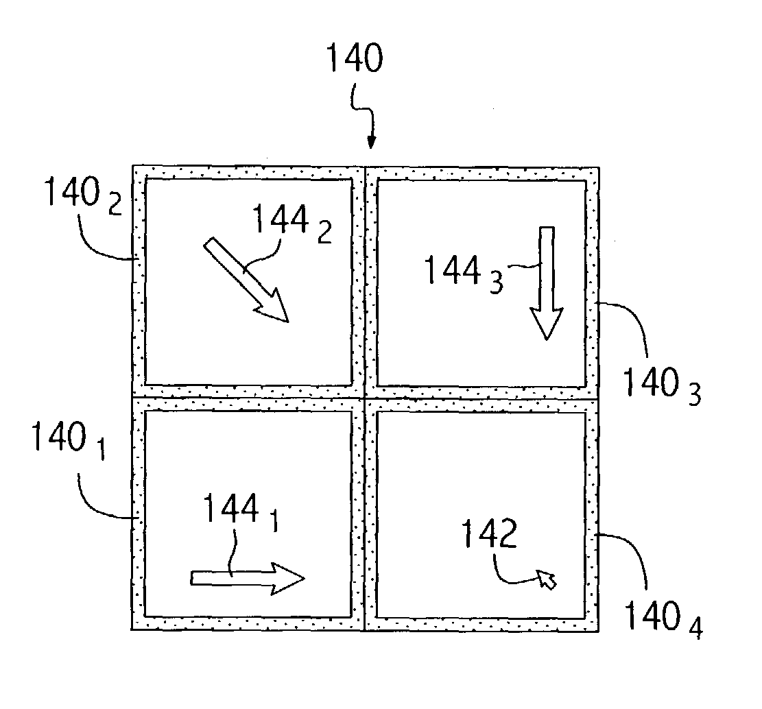
[0024]Embodiments of the present invention provide methods, systems and articles of manufacture for locating a cursor in a computer system having one or more monitors. While described with reference to computer systems having multiple monitors, it will be appreciated that aspects of the present invention may be used to an advantage in computer systems having a single monitor.

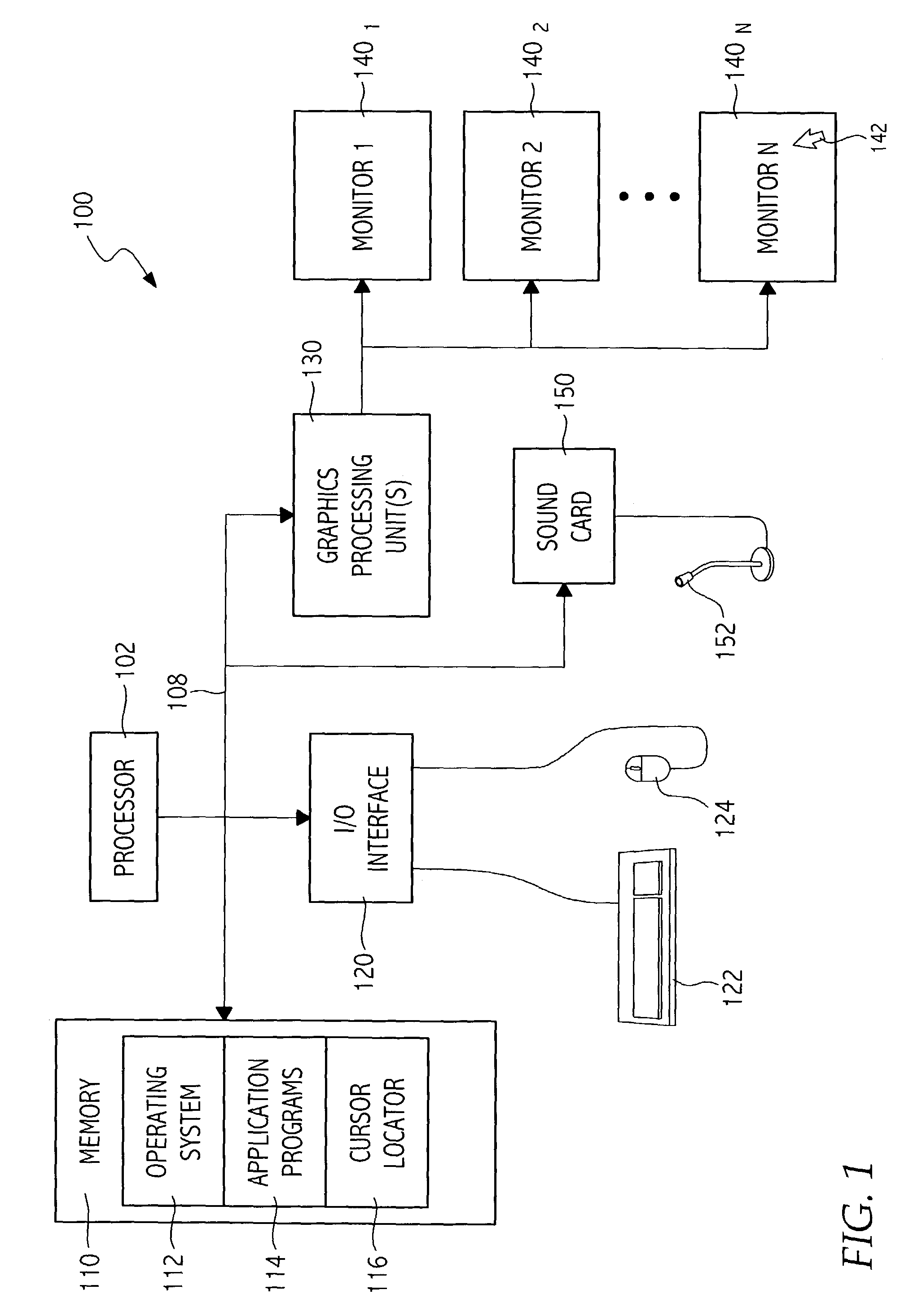
[0025]Embodiments of the present invention may be implemented as a program product for use with a computer system such as, for example, the computer system 100 shown in FIG. 1. The program product may include a program which, when executed by a processor 102, performs functions of the embodiments (including the methods described herein). The program product can be contained on a variety of signal-bearing media, including, but not limited to, non-writable storage media (e.g., read-only memory devices, such as CD-ROM disks), alterable information stored on writable storage media (e.g., floppy disks, CD-R / W disks),...


PUM


Abstract

Embodiments of the present invention generally provide methods, systems, and articles of manufacture for locating a cursor displayed on one of a set of one or more monitors. According to some embodiments, in response to receiving specified user input, visual indication of the location of the cursor may be provided on one or more monitors not containing the cursor. Visual indication of the location of the cursor may also be provided on the monitoring containing the cursor. The specified user input may include any type of suitable user input, such as mouse movements, keystroke sequences (e.g., hot keys,) and / or audio input (e.g., voice commands). For some embodiments, parameters used for locating the cursor (e.g., the specified user input, sensitivity to mouse movements, etc.) may be specified by a user, for example, via a graphical user interface (GUI) screen.

Description

BACKGROUND[0001]1. Field of the Invention[0002]Embodiments of the present invention generally relate to computer systems and, more particularly to locating a cursor in a computer system with multiple monitors.[0003]2. Description of the Related Art[0004]Computer systems have traditionally included a single monitor with a limited screen area. As users run more and more applications and process more information, they require larger screen areas. In other words, a user may be much more productive if more of the information can be displayed without having to change screen views (i.e., toggle) to find desired information. However, monitors with larger screen areas are expensive, and the price increase is typically disproportionate with the increase in screen area.[0005]However, recent developments in computer graphics technology have resulted in a cost effective technique for increasing screen area through the use of multiple monitors. There are at least two approaches for driving multip...

Claims


Application Information

Patent Timeline
Patent Type & Authority Patents(United States)
IPC IPC(8): G09G5/08G06F3/023G06F3/038
CPCG06F3/038G06F3/04892G06F2203/04801
Inventor DE WAAL, ABRAHAM B.
Owner NVIDIA CORP
Why Eureka
Try Eureka