Night-day boresight with adjustable wedge-prism assembly

a wedge-prism assembly and night-day boresight technology, applied in the field of boresights, can solve the problems of time-consuming and not always convenient, troublesome to swap boresights, and trial and error, and achieve the effects of reducing or eliminating an image shi

Active Publication Date: 2006-11-28
KNIGHT VISION LLLP
View PDF9 Cites 22 Cited by
  • Summary
  • Abstract
  • Description
  • Claims
  • Application Information

AI Technical Summary

Benefits of technology

[0012]A second aspect of the invention is an image-shift adjustor apparatus for an in-line boresight that has a first optical system and a downstream second optical system. The first and second optical systems may be, for example, night optics and day optics, respectively. The apparatus includes first and second opposing wedge prisms arranged between the first and second optical systems. The wedge prisms are independently rotatable so as to reduce or eliminate an image shift in the second optical system caused by the first optical system.
[0013]A third aspect of the invention is a method of aligning a boresight having in-line night optics and day optics. The method includes determining a first boresight alignment by aligning the day optics to a desired bullet impact point on a target. The method also includes adding the night optics and an adjustable wedge-prism assembly in line with and upstream of the day optics. The assembly has first and second opposing wedge prisms and is arranged between the night optics and the day optics. The method further includes determining an image shift in the desired bullet impact point due to the presence of the night optics. The method also includes adjusting the adjustable wedge-prism assembly to reduce or eliminate the image shift.
[0014]A fourth aspect of the invention is a method of reducing or eliminating an image shift in an in-line boresight that has a first optical system and a downstream second optical system. The method includes arranging first and second opposing and independently rotatable wedge prisms between the first and second optical systems. The method further includes rotating at least one of the wedge prisms so as to reduce the image shift.

Problems solved by technology

Finding the proper boresight alignment for a given set of conditions often involves trial and error, which is time consuming and not always convenient.
However, this requires “rezeroing” each boresight every time it is installed on the weapon.
Also, it is not always convenient to swap boresights, such as in combat or hunting situations since, among other things, there is often precious little time to rezero and align (e.g., by shooting at a target) after replacing one boresight with another.
While this approach does not require physically swapping the night and day optics, it is still problematic because it requires boresight realignment when switching from the night optics to the day optics.
Unfortunately, this approach is not preferred because the user has a different set of adjustments when using the night optics and the day optics.
While this can work in principle, it adds cost to the assembly and testing, with the latter having to be performed frequently until the assembly “settles” due to weapon shock.
While this is a straightforward solution to reducing or eliminating the resultant image shift, it is not desirable because realignment needs to be performed every time the night optics is mounted and dismounted.

Method used


Image

  • Night-day boresight with adjustable wedge-prism assembly
  • Night-day boresight with adjustable wedge-prism assembly
  • Night-day boresight with adjustable wedge-prism assembly

Examples


Embodiment Construction

Apparatus

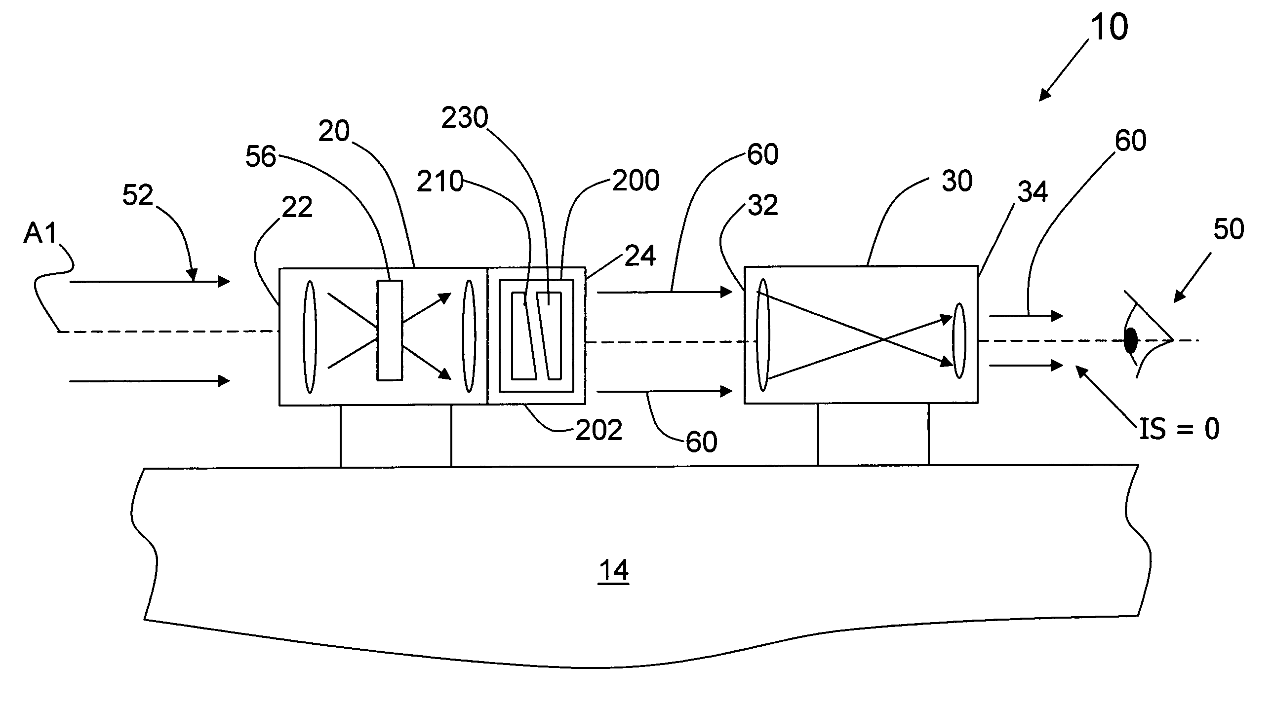
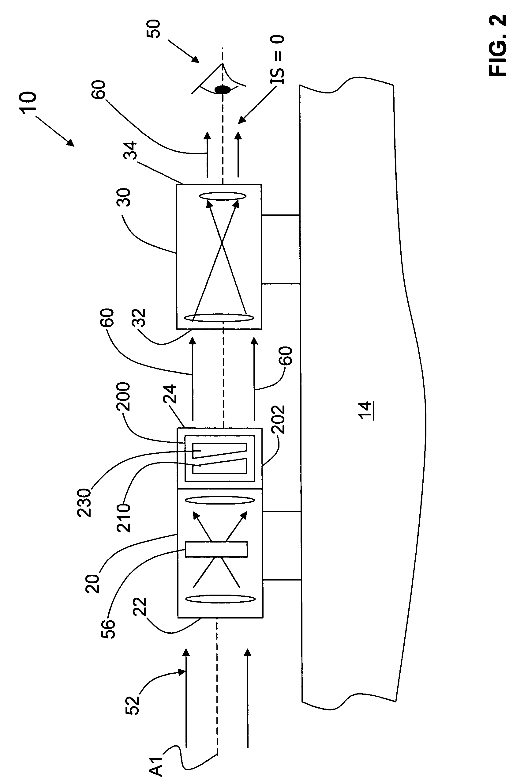
[0022]FIG. 2 is a schematic diagram similar to that of FIG. 1, further including a adjustable wedge-prism assembly 200 arranged in the optical path between day optics 30 and night optics 20. In an example embodiment, adjustable wedge-prism assembly 200 is arranged immediately adjacent output end 24 of night optics 20, as shown. FIG. 3 is a close-up side view of adjustable wedge-prism assembly 200 (dashed line) as held in an outer housing 202. FIG. 4 is a cross-sectional view of adjustable wedge-prism assembly 200 and outer housing 202 taken along the line 4-4.

[0023]With particular reference to FIGS. 2 and 4, in an example embodiment, adjustable wedge-prism assembly 200 includes a first wedge prism 210 having a planar surface 212 perpendicular to axis A1. Prism 210 also includes a planar wedge surface 214 opposite perpendicular planer surface 212 and having a wedge angle θ1 relative to axis A1. Wedge prism 210 has a thick end 220 and a thin end 222.

[0024]Assembly 200 also in...


PUM


Abstract

An in-line night-day boresight with an adjustable wedge-prism assembly is disclosed. The adjustable wedge-prism assembly includes two opposing wedge prisms that are axially rotatable relative to each other. The assembly is arranged in the optical path between the night optics and the day optics. The adjustable wedge-prism assembly allows for compensation of image shift errors introduced by the night optics due to manufacturing errors in the night optics. This in turn allows for a cost-effective and easily aligned in-line night-day boresight.

Description

FIELD OF THE INVENTION[0001]The present invention relates to boresights, and in particular relates to in-line night-day boresights, and apparatus and methods for aligning sameBACKGROUND OF THE INVENTION[0002]Boresighting optical systems (“boresights”) are used for long-range weapons, such as rifles, to allow the weapon's user to view a target and align the weapon relative to the target, e.g., to a select bullet impact point. A typical boresight includes an alignment mechanism used to align the weapon and boresight relative to the target, e.g., to the desired bullet impact point. An example alignment mechanism is a cross-hair reticle wherein the boresight is adjusted (“aligned”) so that the reticle cross-hairs match the desired bullet impact point for a given target distance. Additional adjustments may be made to realign the boresight to the bullet impact point to take into account such factors as windage, distance, and bullet caliber. Finding the proper boresight alignment for a giv...

Claims


Application Information

Patent Timeline
Patent Type & Authority Patents(United States)
IPC IPC(8): G02B23/12
CPCF41G1/32G02B23/14F41G3/326
Inventor GREENSLADE, KEN
Owner KNIGHT VISION LLLP
Why Eureka
Try Eureka