Ophthalmoscopy lens system

a technology of ophthalmoscopy and lens system, which is applied in the field of ophthalmoscopy lens system, can solve the problems of increasing pressure and increasing pressure in the eye, and achieves the effect of improving pressure and pressur

Inactive Publication Date: 2006-12-05
ROSS III DENWOOD F +1
View PDF5 Cites 48 Cited by
  • Summary
  • Abstract
  • Description
  • Claims
  • Application Information

AI Technical Summary

Problems solved by technology

If the anterior chamber angle is narrowed, fluid flow may be obstructed resulting in an increase in pressure within the eye.
Such an increase in pressure is often associated with glaucoma.

Method used


Image

  • Ophthalmoscopy lens system
  • Ophthalmoscopy lens system
  • Ophthalmoscopy lens system

Examples


example 1

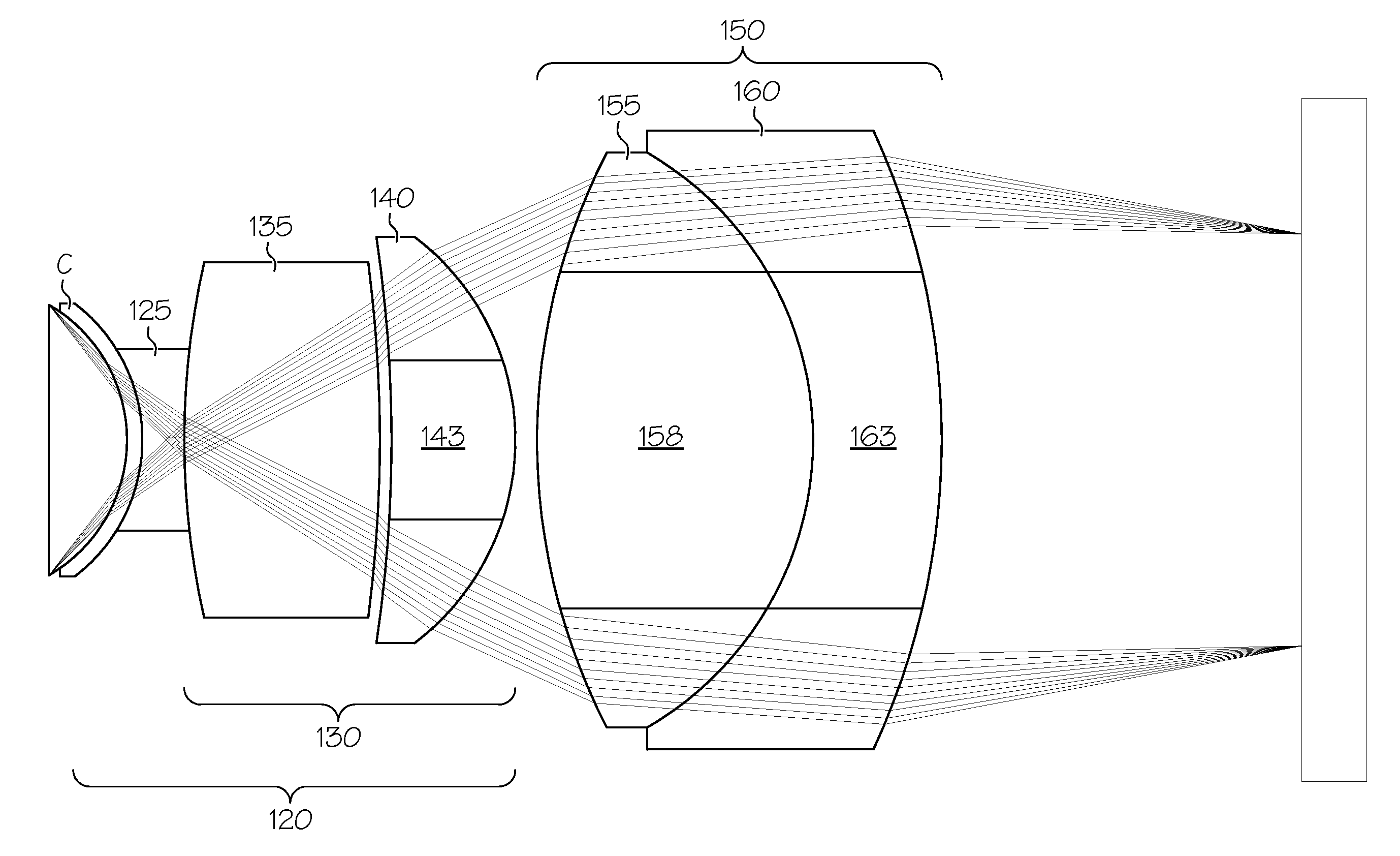
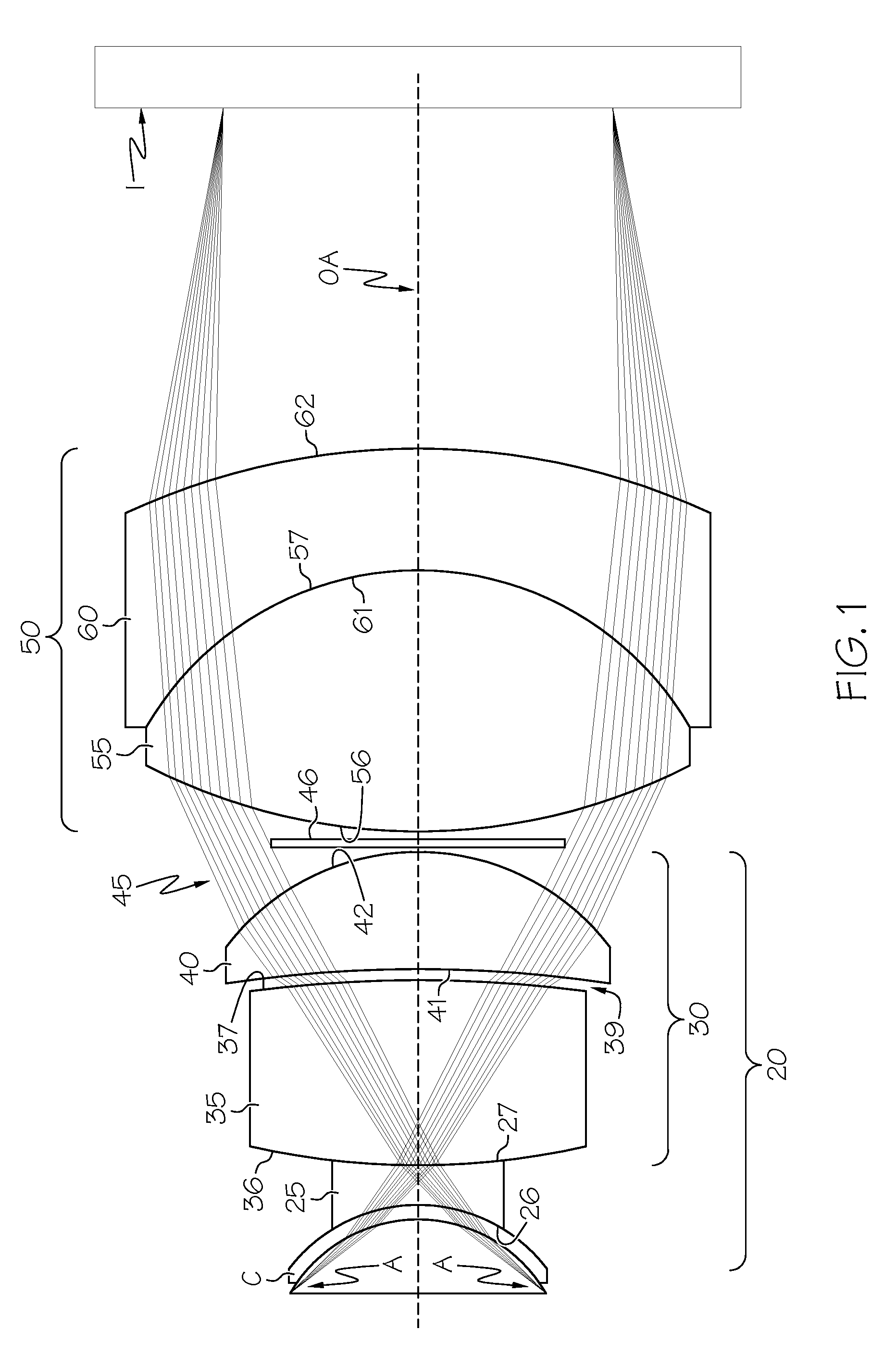
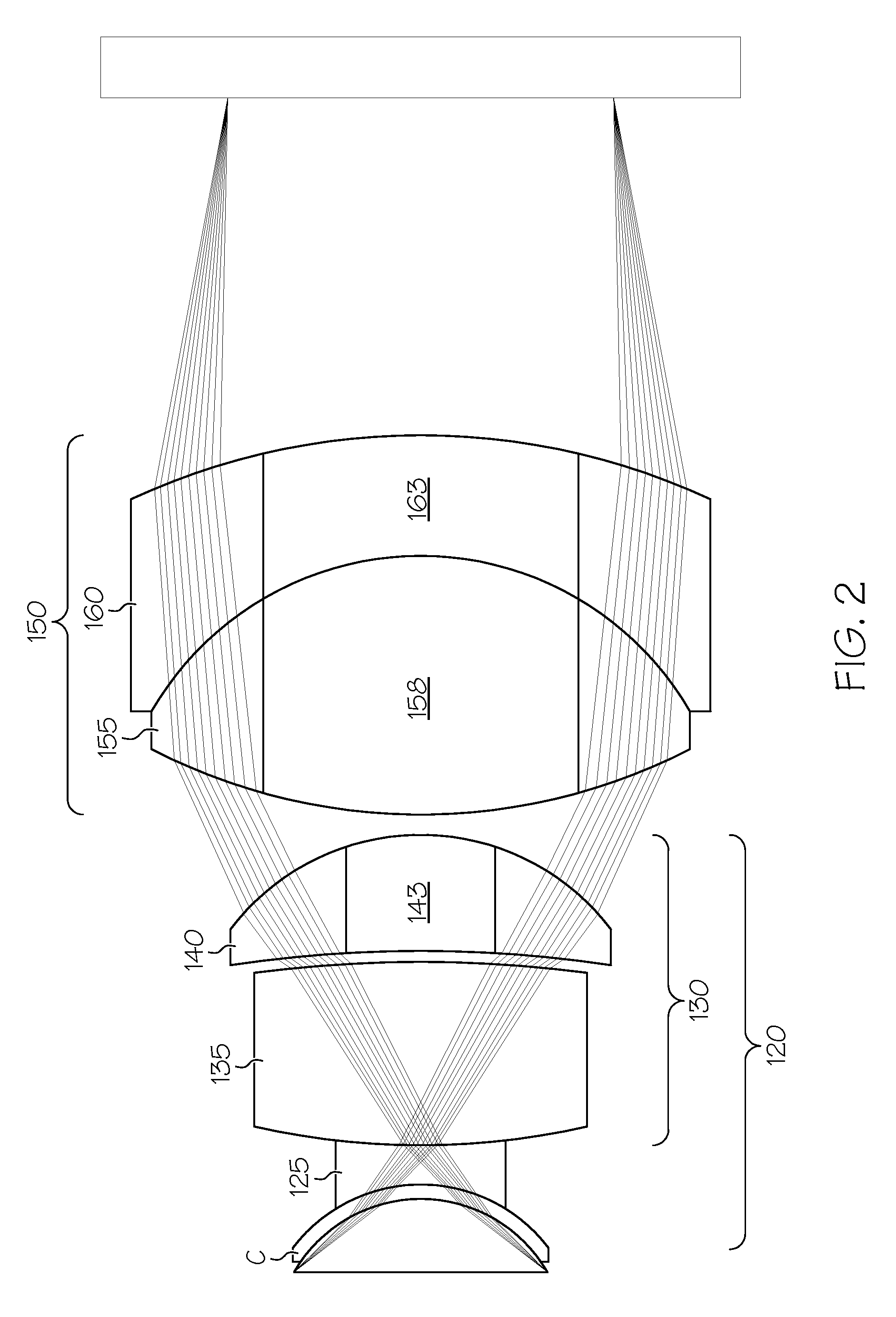
[0038]Although the opthalmoscopy lens system described above can be fabricated in a variety of configurations, applicant has fabricated and tested a specific embodiment of a lens system according to the present invention (and in accordance with the configuration shown in FIG. 1). The prescription for this embodiment of the lens system of FIG. 1 is provided in the tables below (wherein the name of the various glasses is that used by Schott). In the first table, the radius refers to the apical radius of the surface at the point where the surface crosses the optical axis. “CX” denotes a convex surface, and “CV” denotes a concave surface.

[0039]

RadiusThicknessDiameterConicSurfaceMaterial(mm)(mm)(mm)Constant (k)26Acrylic7.81CV213−0.2536SFL5733.42CX8.713039air space58.41CX0.38613041LAK868.745CV5.7618045air space11.323CX0.83718056LAFN2822.026CX12.525.5−3.75561SFL5714.589CV5.625.506233.73CX27.50

Index of refraction data (at 20° C. and 1.0 atm) for the above surfaces is provided below:

[0040]

Wa...


PUM


Abstract

A gonioscopic lens system which provides a real image of the anterior chamber angle of a patient's eye. The lens system includes a first lens group having a concave posterior surface configured to be placed on a patient's eye, a second lens group optically aligned with the first lens group; and a stop positioned between the first and second lens groups. An achromatic gonioscopic lens system which provides a real image of the anterior chamber angle of a patient's eye is also provided, as well as an ophthalmoscopy lens system for viewing both the anterior chamber angle and the retina of a patient's eye.

Description

[0001]This application claims the benefit of U.S. Provisional Application Ser. No. 60 / 419,447 filed on Oct. 18, 2002, the entire disclosure of which is hereby incorporated herein by reference.BACKGROUND OF THE INVENTION[0002]1. Field of the Invention[0003]The present invention relates to ophthalmoscopy lens systems, particularly those employed with a slit lamp or other biomicroscope for the diagnosis and / or treatment of the eye.[0004]2. Description of Related Art[0005]During the diagnosis and treatment of the eye, it is typically necessary to provide a means for viewing various structures within the eye. Various ophthalmoscopy lens systems have been developed for this purpose. By way of example, “indirect” ophthalmoscopy lens systems have been developed. Such lens systems produce an aerial image of structures within the patient's eye, and such real images may be viewed using, for example, a slit lamp biomicroscope or other indirect ophthalmoscope. Direct ophthalmoscopy lens systems,...

Claims


Application Information

Patent Timeline
Patent Type & Authority Patents(United States)
IPC IPC(8): A61B3/125
CPCA61B3/117G02B9/08
Inventor ROSS, III, DENWOOD F.JONES, LARRY
Owner ROSS III DENWOOD F
Why Eureka
Try Eureka