
Exhaust gas purification system

a technology of exhaust gas and purification system, which is applied in the direction of exhaust treatment electric control, electrical control, separation process, etc., can solve the problems of increasing pressure loss, lowering processing performance, and increasing pressure loss

Inactive Publication Date: 2006-12-12
TOYOTA JIDOSHA KK
View PDF11 Cites 1 Cited by
  • Summary
  • Abstract
  • Description
  • Claims
  • Application Information

AI Technical Summary

Benefits of technology

[0008]An object of the present invention is to provide means capable of restricting the discharge of non-treated PM so that the drawbacks in the conventional electrostatic type apparatus are minimized.

Problems solved by technology

Such a filtration type apparatus has a drawback in that a pressure loss increases due to the exhaust resistance when the exhaust gas passes the filter.
According to the electrostatic attraction type apparatus, however, there is a problem in that incompletely burnt PM are liable to generate as the deposit thereof increases and particularly, when an attracting honeycomb structure body is provided in the outer circumferential electrode, ash remaining after the combustion treatment causes the increase in pressure loss due to the reduction of a cell cross-section (opening area), resulting in the lowering of processing performance.
A particle diameter of the attracted PM increases as the deposition progresses by the mutual bonding of the respective particulates via HC component, H2O component or others, whereby there is a risk in that PM may be peeled off from the attracting surface before it is processed by a high voltage and released downstream of the apparatus.

Method used


Image

  • Exhaust gas purification system
  • Exhaust gas purification system
  • Exhaust gas purification system

Examples


Embodiment Construction

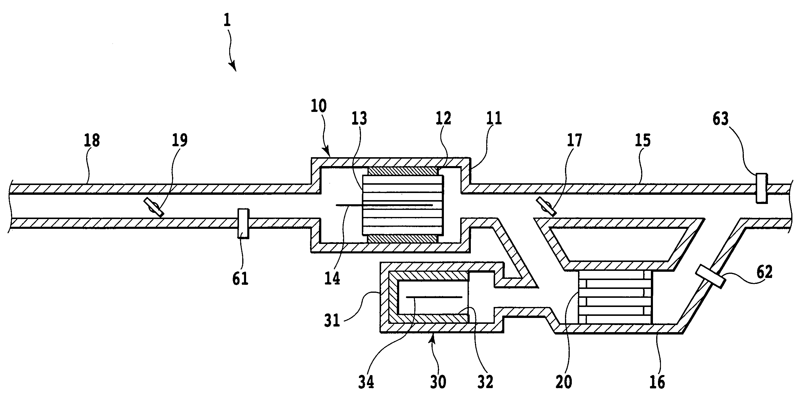
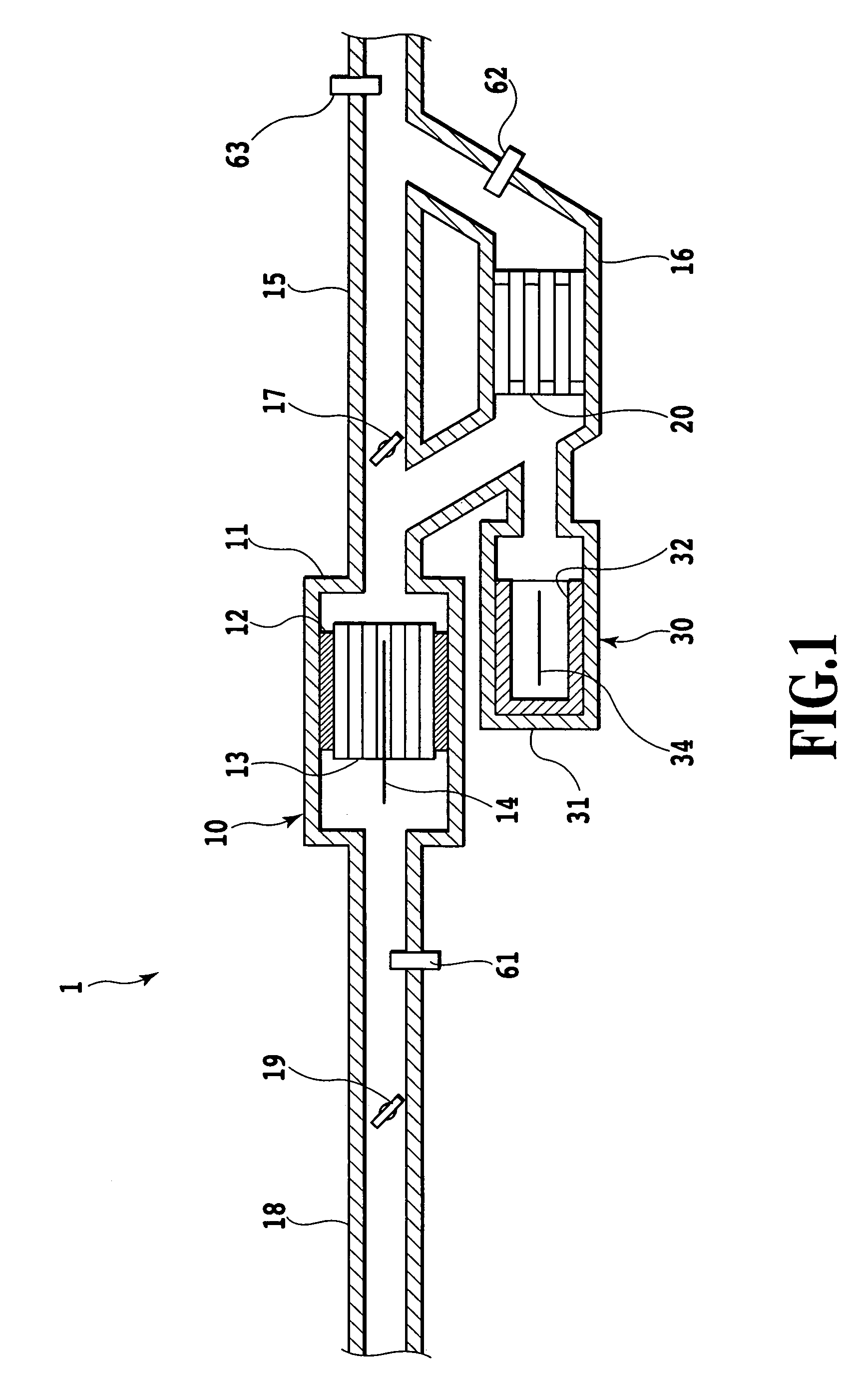
[0018]An embodiment of the present invention will be described below with reference to the attached drawings. This embodiment of the exhaust gas purification system is suitably applicable to an automobile, incorporated into an exhaust passage of an engine (not shown) for cleaning exhaust gas discharged from a combustion chamber of the engine.

[0019]As shown in FIG. 1, the exhaust gas purification system 1 includes a catching reactor 10 formed as an electrostatic attraction type plasma reactor and a PM filter 20 formed as a filtration type filter. A auxiliary exhaust path 16 is connected in a branched manner to a midway point of a main exhaust path 15 provided on a exit side of the catching reactor 10, and a PM filter is provided at a midway point of the auxiliary exhaust path 15. A terminal end of the auxiliary exhaust path 16 joins to the main exhaust path 15.

[0020]The catching reactor 10 attracts and processes particulate matters in the exhaust gas discharged from the engine by the...


PUM

PropertyMeasurementUnit
electrostatic forceaaaaaaaaaa
rotational speedaaaaaaaaaa
flow rateaaaaaaaaaa

Abstract

An exhaust gas purification system including a catching reactor for attracting particulate matters in an exhaust gas from an engine by electrostatic force, a main exhaust path and an auxiliary exhaust path provided on the exit side of the catching reactor, a PM filter provided in the auxiliary exhaust path for filtrating and processing the exhaust gas, and a flow path control valve for selectively connecting the exit side of the catching reactor to the main exhaust path or the auxiliary exhaust path.

Description

[0001]This application claims priority from Japanese Patent Application No. 2003-359800 filed Oct. 20, 2003, which is incorporated hereinto by reference.BACKGROUND OF THE INVENTION[0002]1. Field of the Invention[0003]The present invention relates to an exhaust gas purification system used in an internal combustion engine for purifying exhaust gas.[0004]2. Description of the Related Art[0005]As a technique for purifying exhaust gas discharged from an internal combustion engine, an exhaust gas purification system (a plasma reactor) has been conventionally proposed, using plasma generated by applying a high voltage to a pair of opposed electrodes. For example, Japanese Patent Application Laid-open No. 2001-295629 discloses a filtration type apparatus disposed in a flow path of the exhaust gas, which is formed by sandwiching a fibrous filter between a pair of metallic nets constituting an electrode. According to this apparatus, particulate matters (PM) in the exhaust gas caught by the f...

Claims


Application Information

Patent Timeline
Patent Type & Authority Patents(United States)
IPC IPC(8): F01N3/00F02D45/00B01D46/42B01D53/94B01J19/08B03C3/36B03C3/40B03C3/41B03C3/49B03C3/60F01N3/01F01N3/02F01N3/022F01N3/031F01N3/033F01N9/00
CPCB03C3/36F01N3/01F01N3/033F01N9/00F01N9/002B03C2201/30F01N3/0222F01N3/031F01N2240/28F01N2260/04F01N2330/14Y02T10/20Y02T10/47Y10S55/30Y02T10/12Y02T10/40
Inventor YAHAGI, HIDEO
Owner TOYOTA JIDOSHA KK
Learn More