Laser light source device and video display device

a laser light source and video display technology, applied in the direction of picture reproducers, picture reproducers using projection devices, instruments, etc., can solve the problems of difficult to form an inexpensive laser light source device, unsuitable stepwise arrangement of mirrors, and more sensitive variations in performance of distant laser modules, so as to minimize the enlargement of cross sections, shorten the length of the entire optical path, and minimize the type of components

Inactive Publication Date: 2018-09-25
MITSUBISHI ELECTRIC CORP
View PDF20 Cites 0 Cited by
  • Summary
  • Abstract
  • Description
  • Claims
  • Application Information

AI Technical Summary

Benefits of technology

[0012]The laser light source device according to the present invention is configured such that the plurality of laser light source units are arranged in series, and that the first reflection mirror and second reflection mirror disposed on the optical axes of the respective rays of laser light reflect the individual rays of laser light in the same direction. Such a configuration enables spatial combination of the rays of laser light with a minimum increase in etendue while keeping the optical axes parallel with each other.
[0013]Using the second reflection mirror provides a shorter length of the entire optical path than projecting the rays of laser light in a direction in which the laser light source units are disposed by using the first reflection mirror alone. This minimizes the enlargement of the cross sections of the rays of laser light due to divergence angles, to thus achieve a further small laser light source device.
[0014]The individual laser light source units are configured such that the first reflection mirrors of the same type are held by the respective mirror holders of the same type. Such a configuration minimizes types of components, provides an inexpensive, small and easy-to-be-assembled laser light source device, and further provides an inexpensive and small video display device provided with the same.

Problems solved by technology

Unfortunately, the use of the mirror means, which are stepwise arranged, the mirror means that are more remote from the laser modules are more sensitive to variations in performance due to the shapes of components and to the accuracy of their positions.
It is thus difficult to form an inexpensive laser light source device.
Thus, the stepwise-arranged mirror means are unfortunately unsuitable in an effort to further increase the output of the laser light source device.

Method used


Image

  • Laser light source device and video display device
  • Laser light source device and video display device
  • Laser light source device and video display device

Examples


first embodiment

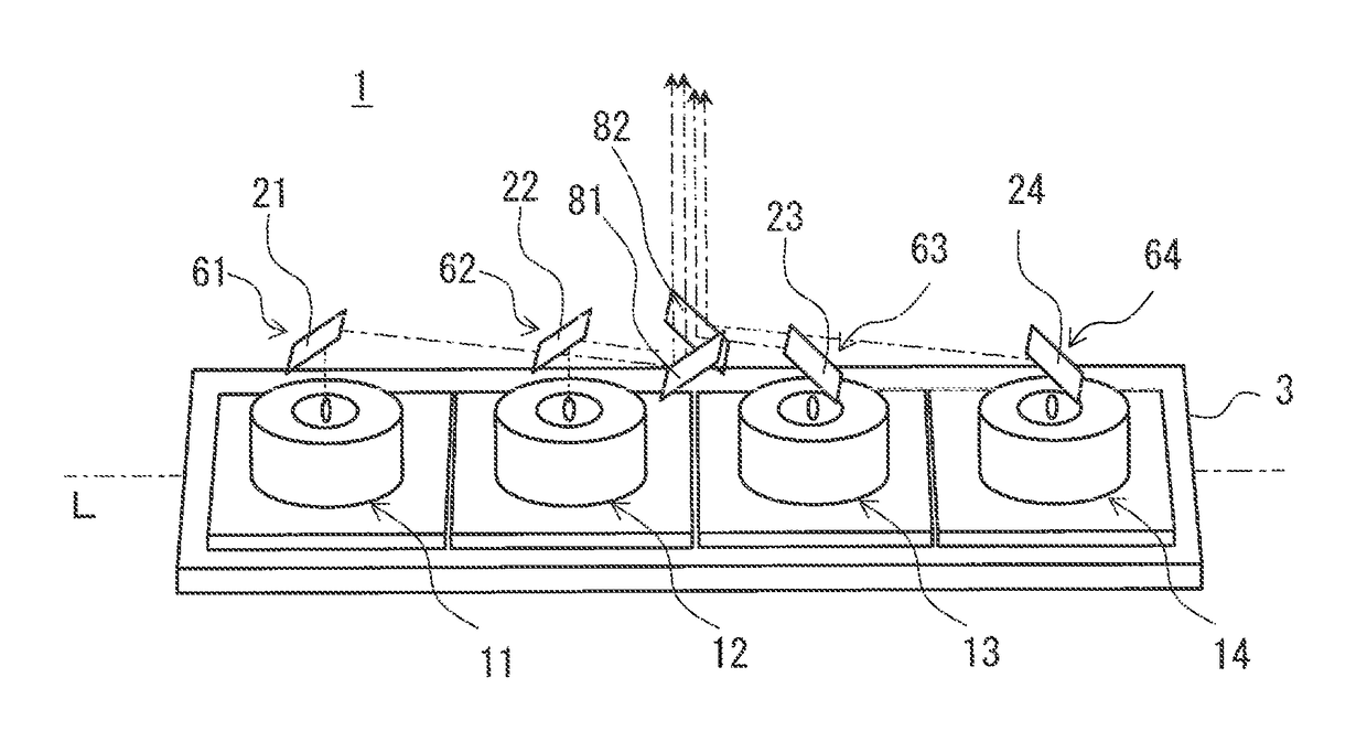
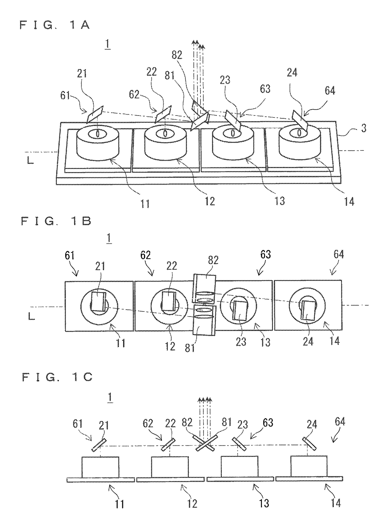
[0031]The following describes a first embodiment of the present invention with reference to the drawings. FIGS. 1A, 1B, and IC are schematic diagrams of a configuration of a laser light source device 1 according to the first embodiment. FIG. 1A is a perspective view of the laser light source device 1. FIG. 1B is a plan view of the laser light source device 1. FIG. 1C is a side view of the laser light source device 1. It is noted that FIGS. 1B and 1C omit a base plate 3.

[0032]As illustrated in FIGS. 1A, 1B, and 1C, the laser light source device 1 includes laser light source units 61, 62, 63, and 64, and the base plate 3. The laser light source units 61, 62, 63, and 64 respectively include: laser light sources 11, 12, 13, and 14; first reflection mirrors 21, 22, 23, and 24 corresponding one-to-one to the laser light sources 11, 12, 13, and 14; second reflection mirrors 81 and 82; and mirror holders, which are not shown in FIGS. 1A, 1B, and 1C, but the details of which will follow. The...

second embodiment

[0086]The following describes a laser light source device 150 and video display device according to a second embodiment. FIG. 14 is a schematic diagram of a configuration of the video light source device according to the second embodiment. It is noted that in the second embodiment, the same components as those described in the first embodiment are denoted by the same symbols and that the description of the same components is omitted.

[0087]As illustrated in FIG. 14, the video display device according to the second embodiment includes a laser light source device 150, an integrator rod 42 that is an equalization unit, a relay lens 43 that is an illumination optical system, a light valve 5 that is a video display element, and a projection lens 44 that is a projection optical system.

[0088]The laser light source device 150 includes a plurality of (for instance, three) laser light source devices 1, mirrors 220, 230, and 240 that bend the bundles of laser array light from the individual las...


PUM


Abstract

It is an object to provide a small and inexpensive laser light source device capable of efficiently focusing rays of laser light from a plurality of laser light sources so as to increase output, and to provide an inexpensive and small video display device. The plurality of laser light source units are arranged in such manner that the plurality of laser light source units adjacent to each other adjoin each other in series. The laser light source device further includes a second reflection mirror reflecting, in a third direction, a ray of laser light reflected in a second direction. The second reflection mirror is held by a mirror holder belonging to one laser light source unit among the plurality of laser light source units.

Description

TECHNICAL FIELD[0001]The present invention relates to a small and inexpensive laser light source device that spatially combines rays of laser light emitted from a plurality of laser light sources and increases output, and to a video display device provided with such a laser light source device.BACKGROUND ART[0002]Projector apparatuses have recently needed to have higher luminance because such projector apparatuses are used to display projected images on large-screens for, for instance, digital movie theaters or large conference rooms and further for outdoor projection mapping. Some digital movie theaters have been already about to introduce laser projectors provided with laser light source devices. Thus, a high-luminance laser light source is greatly expected. A typical single laser module can increase output within a limited range, and thus in such a high-luminance laser projector, laser beams (rays of laser light) from a plurality of laser modules are efficiently combined to incre...

Claims


Application Information

Patent Timeline
Patent Type & Authority Patents(United States)
IPC IPC(8): G02B27/14G02B27/18G02B27/09H04N9/31
CPCG02B27/14H04N9/3161G02B27/18G02B27/0977G03B21/2013G03B21/2033G03B21/2066H04N9/3164H04N9/3173G03B21/145
Inventor KIJIMA, TAKUMI
Owner MITSUBISHI ELECTRIC CORP
Why Eureka
Try Eureka