Capacitor based force sensor

Active Publication Date: 2006-12-12
3M INNOVATIVE PROPERTIES CO
View PDF16 Cites 135 Cited by
  • Summary
  • Abstract
  • Description
  • Claims
  • Application Information

AI Technical Summary

Problems solved by technology

Among these difficulties are excessive force sensor size, especially the width and thickness of the sensor.
Making a force sensor that has a size practical for use in very thin or very small devices has proven to be very difficult.
Excessive sensitivity to transverse forces that lead to inaccuracy have also been challenging to address in force sensors.
The cost and complexity of force sensors has also been an issue.
Part of the complexity of force sensors is accentuated when trying to make them small enough for the desired force sensor application.
Since conventional force sensors

Method used


Image

  • Capacitor based force sensor
  • Capacitor based force sensor
  • Capacitor based force sensor

Examples


Embodiment Construction

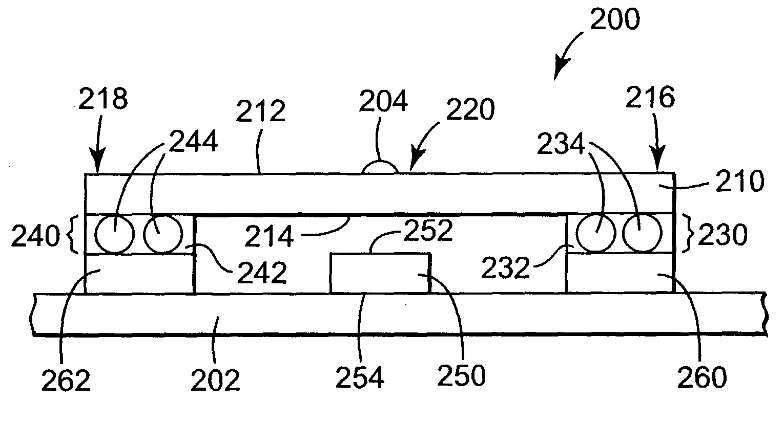
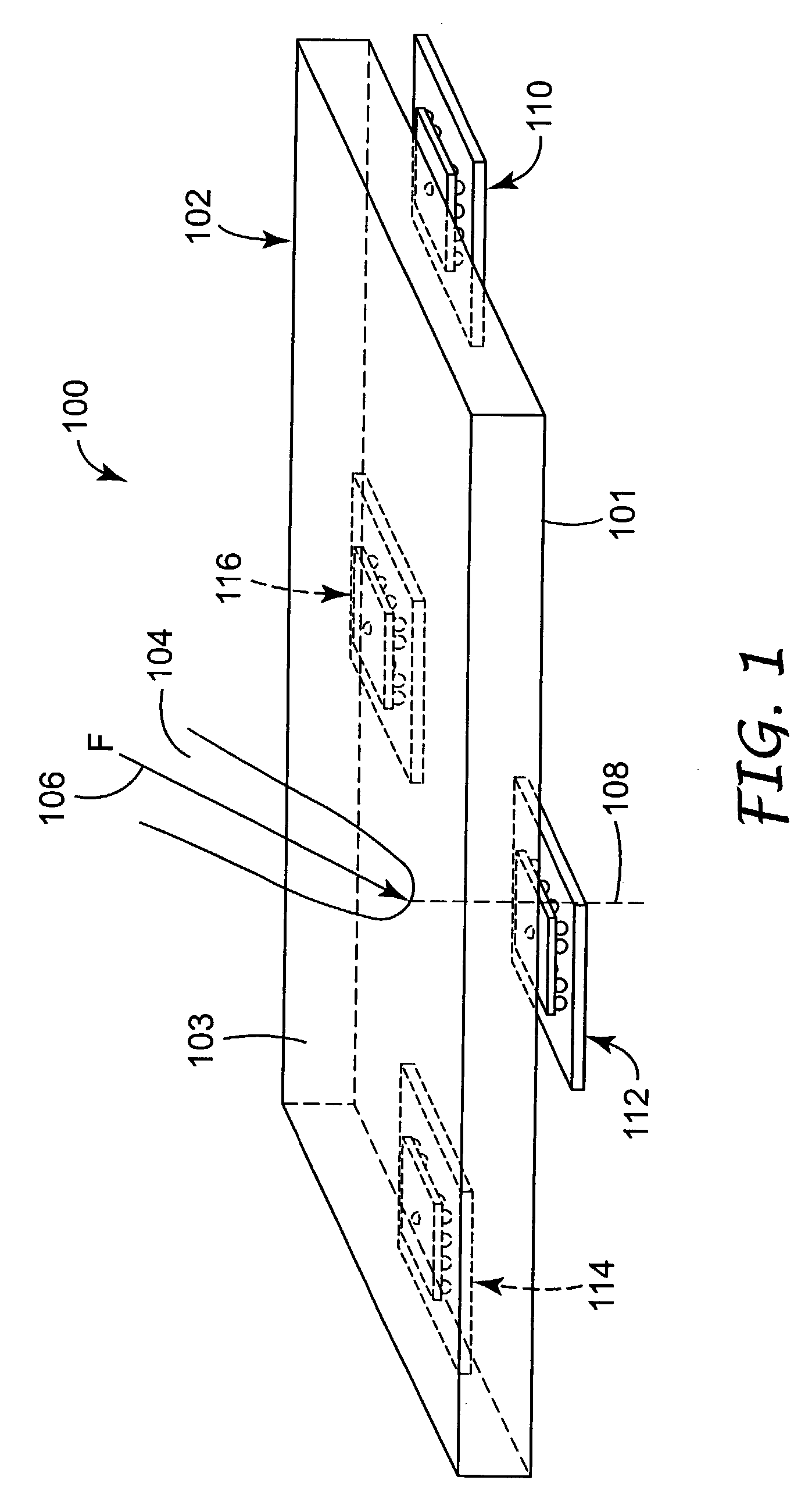
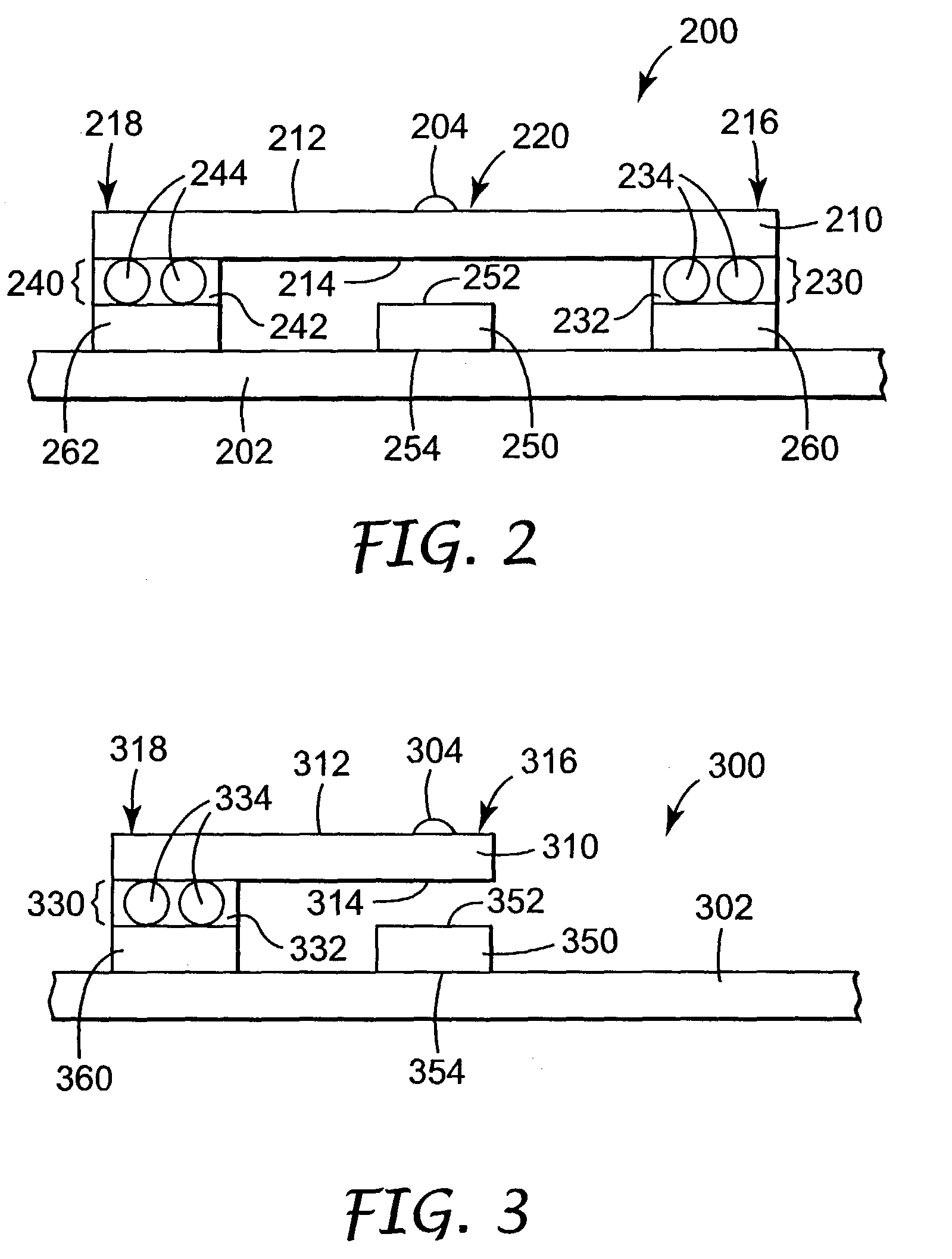
[0019]In one of its aspects, the invention provides a novel capacitive force sensitive device. As described in more detail below, the device of the present invention may provide a more reliable, sensitive and accurate characterization of input forces to the devices. These improved properties of the device may be particularly advantageous when the device is used in small applications such as mobile and hand-held devices, as well as when used in larger applications such as computer monitors and other applications that require a high degree of touch and / or force sensitivity. It is anticipated that the present invention may be more broadly applicable to any application in which a force input must be characterized by, for example, the amplitude, the duration, or acceleration or speed of the force input.

[0020]One aspect of the present invention relates to a capacitive device configured to detect differences in an applied force over a continuous range of applied force including zero force....


PUM


Abstract

The invention provides a novel capacitive device configured to detect differences in an applied force over a continuous range of applied force that includes zero force. The device includes first and second electrodes that are spaced apart a predetermined distance from each other in a rest position. A measurable capacitance exists between the first and second electrodes. Structured elements having a predetermined maximum dimension are positioned in the device to control the predetermined distance between the first and second electrodes. An applied force to the device causes a change in the distance between the first and second electrodes and a related change in the capacitance that can be measured to determine information related to the applied force.

Description

FIELD OF THE INVENTION[0001]The present invention relates to force-based touch sensors, and more particularly relates to controlling spacing between electrodes of a force-based touch sensor.BACKGROUND[0002]The ability to sense and measure the force and / or location of a touch applied to a surface is useful in a variety of contexts. As a result, various systems have been developed in which force sensors are used to measure properties of a force (referred to herein as a “touch force” or an “applied force”) applied to a surface (referred to herein as a “touch surface”). Force sensors typically generate signals in response to the applied force that may be used, for example, to locate the position of an applied force on the touch surface.[0003]Determining the location of an applied force to a touch surface is of particular interest when the touch surface is that of a computer display or a transparent overlay in front of a computer display. Furthermore, the need for small, lightweight, and...

Claims


Application Information

Patent Timeline
IPC IPC(8): G09G5/00G01L1/14
CPCG01L1/142G01L1/146G01L1/14
Inventor KAMRATH, ROBERT F.HAMERLY, MICHAEL E.WEAVER, BILLY L.
Owner 3M INNOVATIVE PROPERTIES CO
Why Eureka
Try Eureka