Method of classification of organs from a tomographic image

a tomographic image and classification method technology, applied in image data processing, diagnostics, sensors, etc., can solve the problem that the identification and analysis of a previous image cannot be reused on a new image, and achieve the effect of extra robustness in classification

Active Publication Date: 2017-11-14
AMRA MEDICAL AB
View PDF21 Cites 2 Cited by
  • Summary
  • Abstract
  • Description
  • Claims
  • Application Information

AI Technical Summary

Benefits of technology

[0011]Extra robustness in the classification may be achieved by using the multi-field data in the water and fat image data sets. For example, the labeled volume elements for an organ in the target image may be labeled as adipose tissue. If the labeled volume elements may be multiplied with the fat image data set, and labeled volume element wrongly transferred into a water area in the target image may automatically be removed.
[0017]In some occasions, when transferring the labeled volume element from the prototype image to the target image, the labeled volume element in the target image may end up close to the boundary of the organ volume. This may cause a wrongly defined organ volume due to a labeling of a volume element which should not be labeled or be part of the organ volume. The method may then comprise a step of manually removing a labeled volume element in the target image. This step may be followed by a redefinition of the organ volume. This may be done by, starting with the remaining labeled volume elements for the current organ, redetermining the extension of the organ volume based on the image properties in the target image. A redetermination of the extension of the organ volume may also be performed when a label is added to a volume element. A label may be added to increase the correctness in the volume extension determination.
[0019]The purpose of the non-rigid co-registration may be to maximize the similarity between the prototype image and the target image. There are several known non-rigid co-registration methods, such as Demons (J.-P. Thirion. Image matching as a diffusion process: an analogy with Maxwell's demons. Medical Image Analysis, 2(3), 1998) and Morphon (Knutsson H, Andersson M. Morphons: Segmentation using elastic canvas and paint on priors. In: IEEE International Conference on Image Processing ICIP 2005, 2005). Any of these may be used to determine a deformation field which defines how the prototype image may be deformed or transformed in order to best fit the target image. Such method may provide a reliable determination of the deformation field, which may increase the probability that a labeled volume element in the prototype image may end up in a corresponding organ in the target image.
[0029]A labeled volume element that is located close to an outer edge of the body in the target image, which edge may represent the skin of the body in the target image, may be determined to be uncertain because it may be a large risk that that label is misplaced. By determining the geometric location of two or more similarly labeled volume elements, a labeled volume element close to the outer edge may be disregarded, i.e. the label may be removed from that volume element. This may increase the correctness of the extension determination of the organ volume for the organ represented by said label.
[0035]Many organs, such as muscles, are similar in size and position between a left and a right half of a human body. The method according to claim 1 may thereby be used for comparing organs in the left half with corresponding organs in the right half. A mirrored copy of the target image may be made to be used as prototype image. The right side of the prototype image may thereby be compared with the left side of the target image, and the left side of the prototype image may be compared with the right side of the target image. By transforming the prototype image to conform to the target image, a difference between corresponding organs in the image, i.e. two sides of the body in the target image, may be detected based on the amount of transformation needed on the prototype image to conform to the target image. For instance, the left thigh muscle in a body may be compared with the right thigh muscle to detect differences in size. Such difference may be important to detect to prevent a future wearing injury. A deformation field may thereby be provided representing the difference between the two sides in the body. Such deformation field may be visualized for the entire images such that differences may be analyzed. A further prototype image may be used for classifying the organs in the target image and / or the mirrored image. The additional prototype image may comprise labeled volume elements as described above, and may be transformed such that the labeled volume elements may be transferred to the target image. The method may thereby provide an automatic process for detecting a difference between the two sides of a body image for a specific, classified, organ. It may further quantify the deformation field for different organs in the target image.
[0040]This organ normalization method may enable a volume rendering of an MR target image using transfer functions. It may further enable an improvement of the Hounsfield attenuation value mapping by providing an improved estimation of the Hounsfield attenuation value in the organs.

Problems solved by technology

The identification and analysis of a previous image is not possible to reuse on a new image.

Method used


Image

  • Method of classification of organs from a tomographic image
  • Method of classification of organs from a tomographic image
  • Method of classification of organs from a tomographic image

Examples


Embodiment Construction

[0067]The present invention will be described more fully hereinafter with reference to the accompanying drawings, in which preferred embodiments of the invention are shown. This invention may, however, be embodied in many different forms and should not be construed as limited to the embodiments set forth herein; rather, these embodiments are provided so that this disclosure will be thorough and complete, and will fully convey the scope of the invention to those skilled in the art. In the drawings, like numbers refer to like elements.

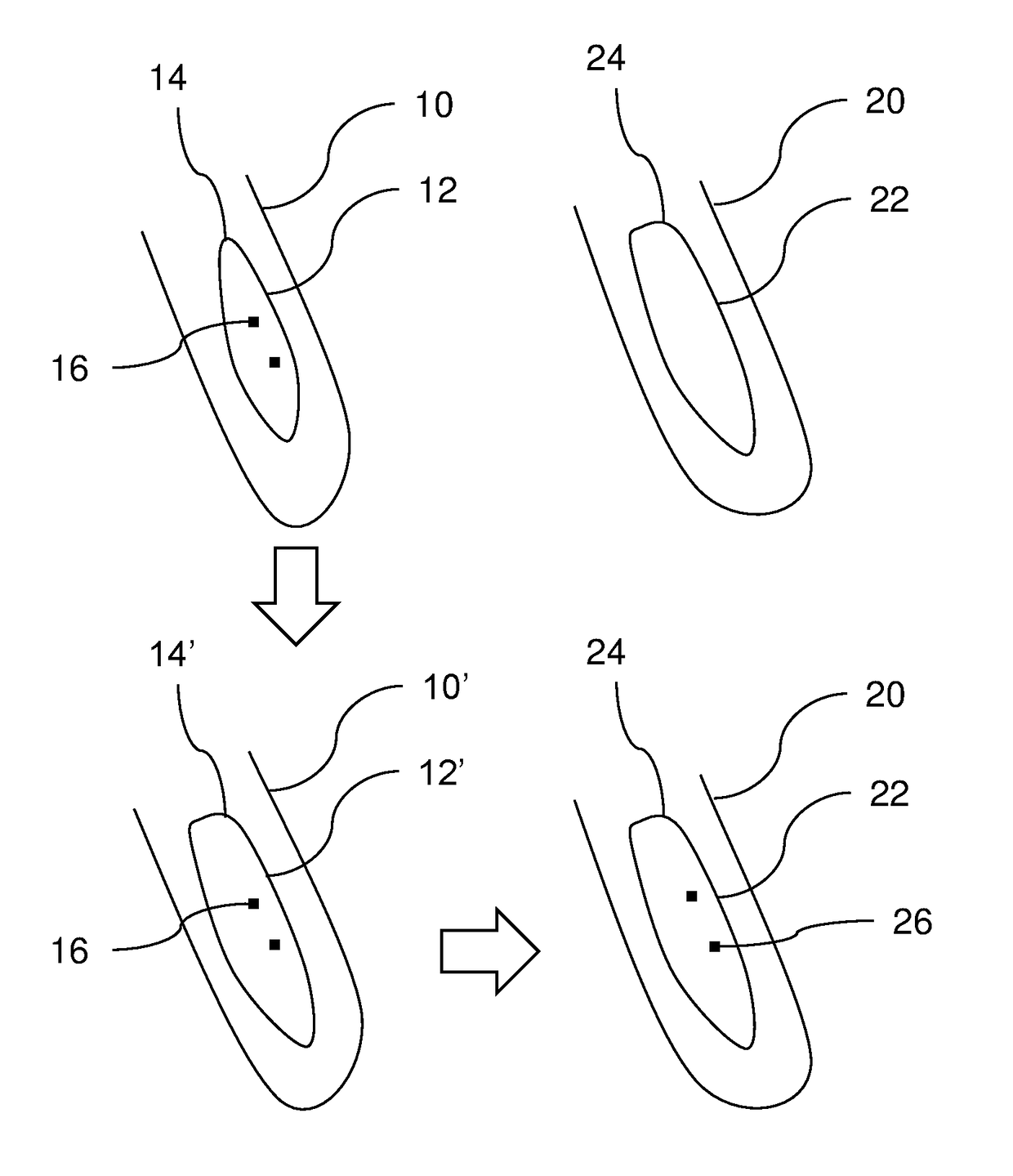
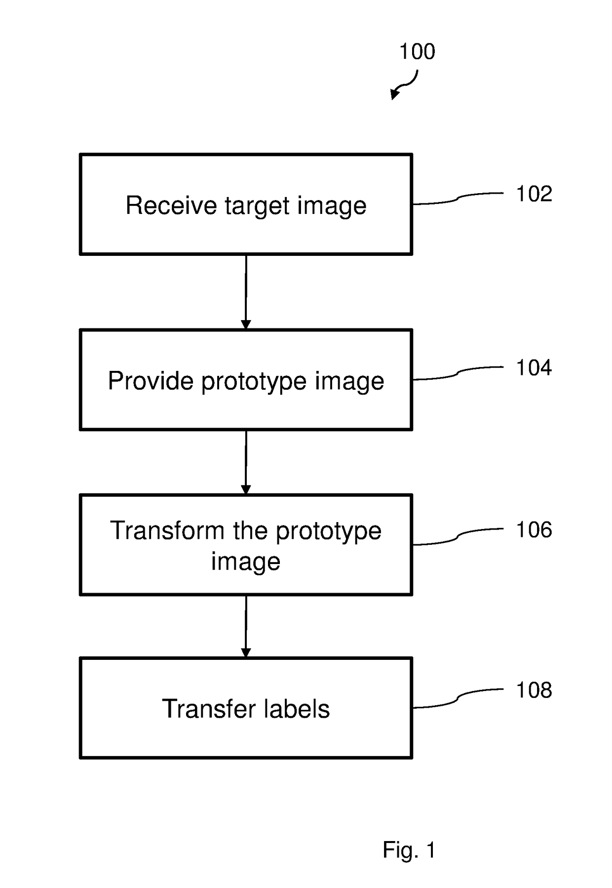
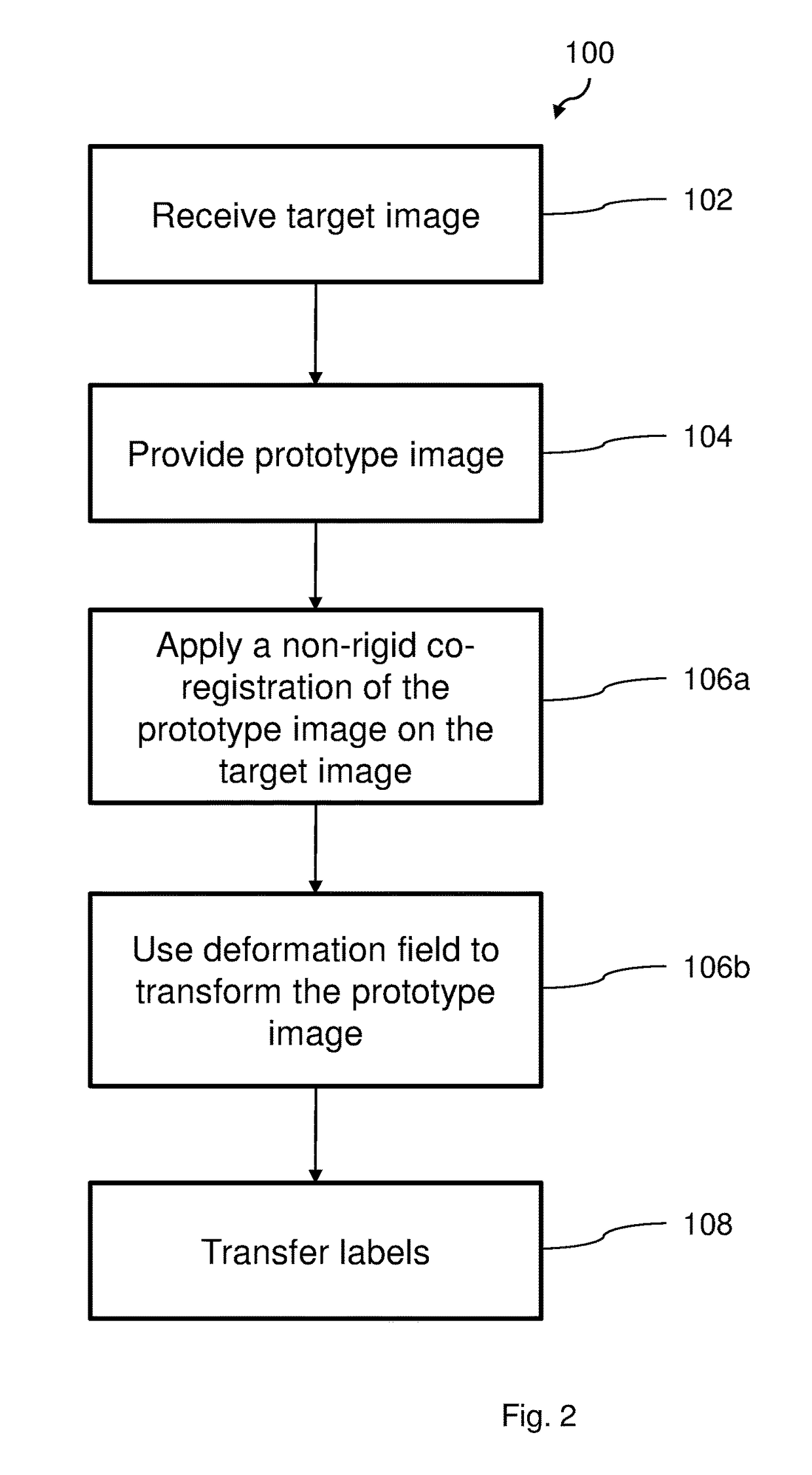
[0068]FIG. 1 illustrates a flow chart of a method 100 according to an embodiment, for registration and classification of organs in a body. The method 100 comprises a first step 102 wherein a 3-dimensional tomographic image is received. The image is provided from a medical scanning apparatus, such as a magnetic resonance (MR) scanner or a computed tomography (CT) scanner. The received tomographic image is a target image, i.e. the image in which organs is ...


PUM


Abstract

The present invention relates to a method for classification of an organ in a tomographic image. The method comprises the steps of receiving (102) a 3-dimensional anatomical tomographic target image comprising a water image data set and a fat image data set, each with a plurality of volume elements, providing (104) a prototype image comprising a 3-dimensional image data set with a plurality of volume elements, wherein a sub-set of the volume elements are given an organ label, transforming (106) the prototype image by applying a deformation field onto the volume elements of the prototype image such that each labeled volume element for a current organ is determined to be equivalent to a location for a volume element in a corresponding organ in the target image, and transferring (108) the labels of the labeled volume elements of the prototype image to corresponding volume elements of the target image.

Description

TECHNICAL FIELD[0001]The present disclosure relates to classification of organs in an image, and especially to the classification of organs in a 3-dimensional anatomical tomographic image comprising a water image data set and a fat image data set.BACKGROUND[0002]In 3-dimensional tomographic medical imaging, identification of different body tissues and organs, such as muscles, is an important part of the medical interpretation of the images. The size, shape and composition, and their variations over time, of different organs can be an important piece of information in many clinical questions. The identification of such features is in general a manual process, which includes manually identifying a specific organ and possibly labeling it in the image. The present image may, after a complete identification and analysis process, comprise a plurality of labels for different organs. Points, or voxels, in the 3-dimensional image may thereby represent a location of an organ.[0003]However, wh...

Claims


Application Information

Patent Timeline
Patent Type & Authority Patents(United States)
IPC IPC(8): G06T7/00A61B5/055G06T7/174A61B6/00G06T7/33G06T7/11A61B6/03
CPCG06T7/0014A61B5/055A61B6/032A61B6/037A61B6/5247G06T7/11G06T7/337G06T7/174G06T2207/30056A61B6/5217G06T2207/10081G06T2207/10088G06T2207/10104
Inventor DAHLQVIST LEINHARD, OLOFBORGA, MAGNUS
Owner AMRA MEDICAL AB
Why Eureka
Try Eureka