Shift control apparatus of automatic transmission of motor vehicle

a technology of automatic transmission and control apparatus, which is applied in the direction of machines/engines, road transportation, and gearing. it can solve the problems of increasing the speed of the input shaft or a temporary drop (or tie-up) of the output torque, the inability to control the engagement pressure of the friction elements with sufficient robustness, and the inability to operate with considerably high accuracy. it can reduce or eliminate the differences among individual apparatuses, reduce or eliminate the effect of shift shocks

Inactive Publication Date: 2006-07-11
TOYOTA JIDOSHA KK +1
View PDF22 Cites 7 Cited by
  • Summary
  • Abstract
  • Description
  • Claims
  • Application Information

AI Technical Summary

Benefits of technology

[0008]It is therefore one object of the invention to provide a shift control apparatus of an automatic transmission with which a clutch-to-clutch downshift during coasting of the vehicle is controlled with sufficiently high robustness with respect to disturbances, such as braking of the vehicle. It is another object of the invention to provide a shift control apparatus of an automatic transmission with which a clutch-to-clutch downshift during coasting is controlled without using high-accuracy control equipment, so that shift shocks are sufficiently reduced even in the event of disturbances, such as braking of the vehicle.
[0010]With the shift control apparatus constructed as described above, the engine speed is increased by a controlled amount based on the difference between the input and output rotation speeds of the fluid coupling device when a clutch-to-clutch downshift is effected during coasting of the vehicle. Since the clutch-to-clutch downshift is carried out during coasting while the vehicle is maintained in the minimal driving state as described above, the hydraulic pressures applied to the friction elements associated with the downshift can be controlled with high accuracy owing to reduced torque variation, and sufficient robustness with respect to disturbances, such as braking of the vehicle, can be achieved without requiring high-accuracy control apparatus.
[0012]With the shift control apparatus as described above, the hydraulic pressures applied to the hydraulically operated friction elements associated with the coast downshift during the shifting period are set in accordance with the minimal driving state. Thus, the engaging pressures for the friction elements can be appropriately controlled during the shifting period, so that the engaging and releasing actions can be accomplished with high accuracy, irrespective of disturbances such as braking, resulting in sufficiently reduced shift shocks.
[0014]With the shift control apparatus constructed as described above, the hydraulic pressures applied to the hydraulically operated friction elements associated with the coast downshift during the shifting period are set in accordance with the minimal driving state. Thus, the engaging pressures for the friction elements can be appropriately controlled during the shifting period, so that the engaging and releasing actions can be accomplished with high accuracy, irrespective of disturbances such as braking, resulting in sufficiently reduced shift shocks. In addition, correcting the hydraulic pressures by learning reduces or eliminates differences among individual apparatus or chronological changes, thus assuring improved accuracy in the engaging / releasing actions and significantly reduced shift shocks.

Problems solved by technology

When the automatic transmission goes through a clutch-to-clutch downshift, a release-side friction element (or offgoing friction element) is released and an engagement-side friction element (or oncoming friction element) is engaged around at the same time, and therefore the transmission tends to suffer from racing (a rapidly increase in the speed) of its input shaft or a temporary drop (or tie-up) of its output torque.
In view of these situations, expensive control equipment that operates with considerably high accuracy may be required to control the engaging pressure for the release-side friction element when it is released and the engaging pressure for the engagement-side friction element when it is engaged.
With generally available control apparatus for use in standard vehicles, however, the engaging pressures for the friction elements cannot be controlled with sufficiently high robustness with respect to disturbances, such as braking of the vehicle, and shift shocks may not be sufficiently reduced or suppressed.

Method used


Image

  • Shift control apparatus of automatic transmission of motor vehicle
  • Shift control apparatus of automatic transmission of motor vehicle
  • Shift control apparatus of automatic transmission of motor vehicle

Examples


Embodiment Construction

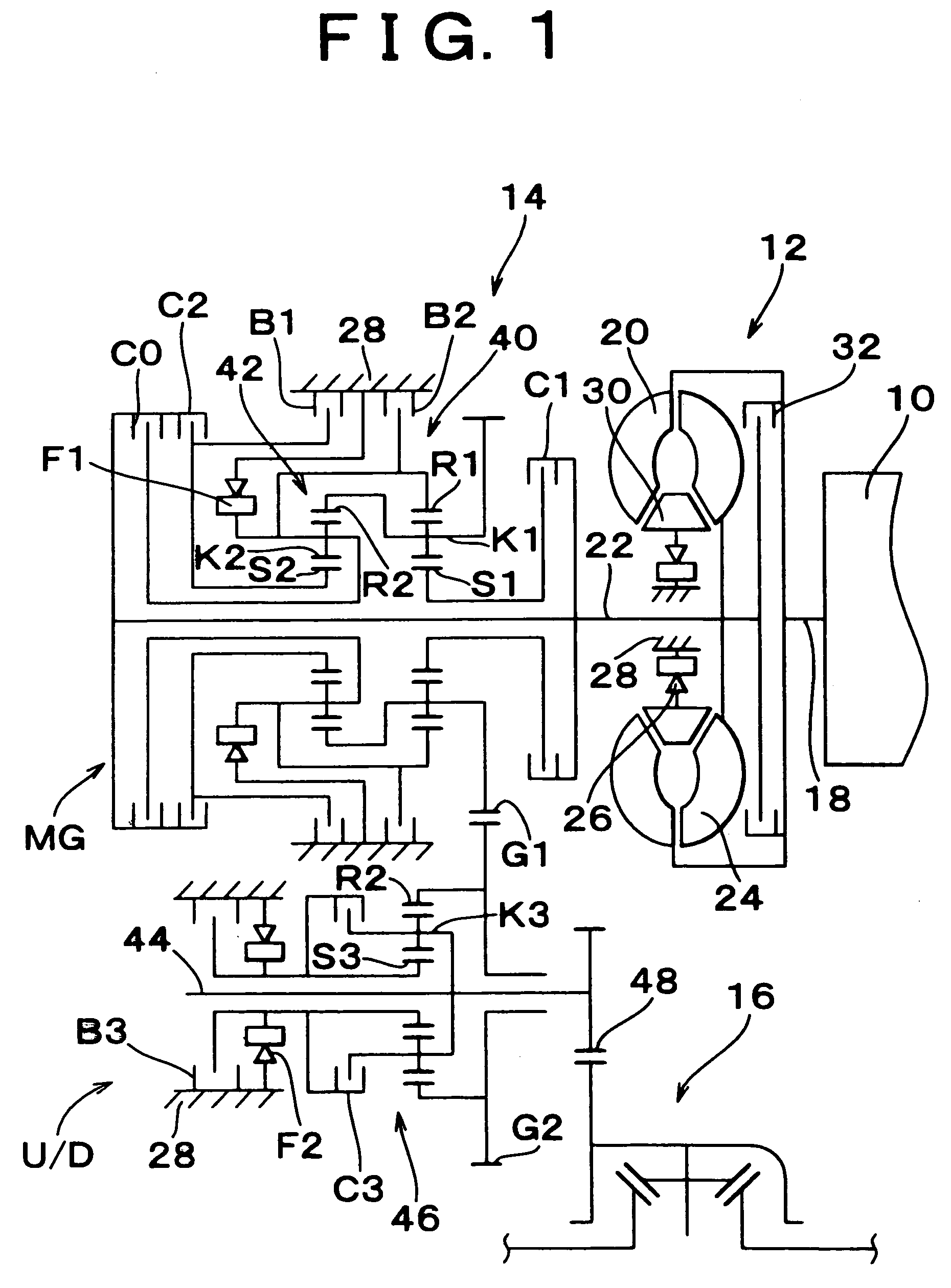
[0037]One exemplary embodiment of the invention will be described in detail with reference to the accompanying drawings. In a motor vehicle as shown in FIG. 1, driving power of an engine 1 is transmitted to driving wheels (i.e., front wheels) (not shown), via a torque converter 12 as a fluid coupling device, an automatic transmission 14 for use in a front-engine front-drive vehicle, and a differential gear device 16. The torque converter 12 includes a pump impeller 20 coupled to a crankshaft 18 of the engine 10, a turbine blade 24 coupled to an input shaft 22 of the automatic transmission 14, a stator 30 fixed to a housing 28 serving as a non-rotating member via a one-way clutch 26, and a lock-up clutch 32 coupled to the input shaft 22 via a damper (not shown).

[0038]The automatic transmission 14 includes single-pinion type first planetary gear set 40 and second planetary gear set 42 disposed coaxially with each other on the input shaft 22 of the transmission 14, a third planetary ge...


PUM


Abstract

A shift control apparatus of an automatic transmission of a motor vehicle to which torque is transmitted from an engine via a fluid coupling device is provided. In the automatic transmission including a plurality of hydraulically operated friction elements, a clutch-to-clutch downshift is carried out during coasting of the vehicle by releasing one of the friction elements and engaging another friction element. A controller of the shift control apparatus detects a difference between input and output rotation speeds of the fluid coupling device, and increases an engine speed by a controlled amount based on the difference between the input and output rotation speeds when the clutch-to-clutch downshift is carried out during coasting of the vehicle, so that the vehicle is brought into a minimal driving state in which the engine speed is slightly higher than the output rotation speed of the fluid coupling device.

Description

[0001]The present application is a divisional application of U.S. patent application Ser. No. 10 / 200,172 filed on Jul. 23, 2002, and now U.S. Pat. Ser. No. 6,740,005.INCORPORATION BY REFERENCE[0002]The disclosures of Japanese Patent Applications No. 2001-234154 filed on Aug. 1, 2001 and No. 2001-233923 filed on Aug. 1, 2001, each including the specification, drawings and abstract, are incorporated herein by reference in its entirety.BACKGROUND OF THE INVENTION[0003]1. Field of the Invention[0004]The invention generally relates to a shift control apparatus of an automatic transmission of a motor vehicle, and more particularly to such a shift control apparatus that effects coast downshift of the transmission while the vehicle is kept in a minimal driving state in which a weak engine brake is applied.[0005]2. Description of Related Art[0006]One type of a downshift control apparatus of an automatic transmission of a motor vehicle has been proposed which keeps the vehicle in a weak engin...

Claims


Application Information

Patent Timeline
Patent Type & Authority Patents(United States)
IPC IPC(8): F16H61/04B60W10/06B60W10/10B60W30/18F02D29/00F16H59/46F16H61/00F16H61/06F16H61/686F16H63/50
CPCB60W10/115B60W30/19F16H61/061B60W10/06B60K2741/065Y10T477/679B60W2520/10B60W2540/12B60W2710/0644B60W2710/0661F16H61/686F16H63/502F16H2059/467F16H2061/0087F16H2200/0047F16H2306/54F16H2061/0496Y10T477/69366Y10T477/675Y10T477/693636Y10T477/6333Y10T477/693958Y10T477/69367B60W10/04B60W10/11B60W30/1819Y02T10/60F16H61/04
Inventor WATANABE, KAZUYUKISATO, TOSHIMITSUAYABE, ATSUSHIKATO, SHINJISAKAMOTO, NAOYUKIKIMURA, HIROMICHISHIBATA, NOBORUNAKAMURA, MITSUHIROOGASAWARA, HIDEAKI
Owner TOYOTA JIDOSHA KK
Why Eureka
Try Eureka