Method and apparatus for volume replication management at planned and unplanned link down

a technology of volume replication and link down, applied in the field of storage area network volume replication, can solve problems such as delay

Inactive Publication Date: 2006-12-19
HITACHI LTD
View PDF14 Cites 14 Cited by
  • Summary
  • Abstract
  • Description
  • Claims
  • Application Information

AI Technical Summary

Benefits of technology

[0006]In another approach for obtaining the point-in-time volume image, if the volume replication function uses log-based volume management, the memorized log sequence number (or its time stamp) at the time of suspension can be used. Thus, the base volume image together with all the logs until that sequence number will enable recovery of the volume image at the time point of the suspension. Another approach, suitable for some uses is to maintain an “old data table.” This table contains all of the data up to the writes occurring just after the link suspension. Using the old data table enables recovery of the volume image at the time of suspension. Finally, another approach is to use the old data tracking log. This tracks the old data as a log on each update to the volume. The choice of which of these methods is employed can be user selectable, or controlled by the storage system administrator, or even controlled dynamically.
[0007]Preferably, in a system having a primary storage volume having first data stored thereon and a secondary storage volume having second data stored thereon, the primary storage volume coupled to the secondary storage volume by a communications link, a method is provided for restoring data after a suspension of the link. The method includes the steps of: upon suspension of the link, maintaining a first image of the first data stored on the primary volume and maintaining a second image of second data stored on the secondary volume. Then updates to the first data and updates to the second data after suspension of the link are tracked. Next the image of the first data is revised to account for the updates to thereby provide a complete first data image for use when the link is restored. The image of the second data is revised to account for the updates to it thereby provide a complete second data image for use when the link is restored. Finally data is copied between the primary volume and the secondary volume when the link is restored to thereby resynchronize the primary volume and the secondary volume.

Problems solved by technology

Such failures would otherwise require a delay while the data is restored from back-up tapes or the like.

Method used


Image

  • Method and apparatus for volume replication management at planned and unplanned link down
  • Method and apparatus for volume replication management at planned and unplanned link down
  • Method and apparatus for volume replication management at planned and unplanned link down

Examples


Embodiment Construction

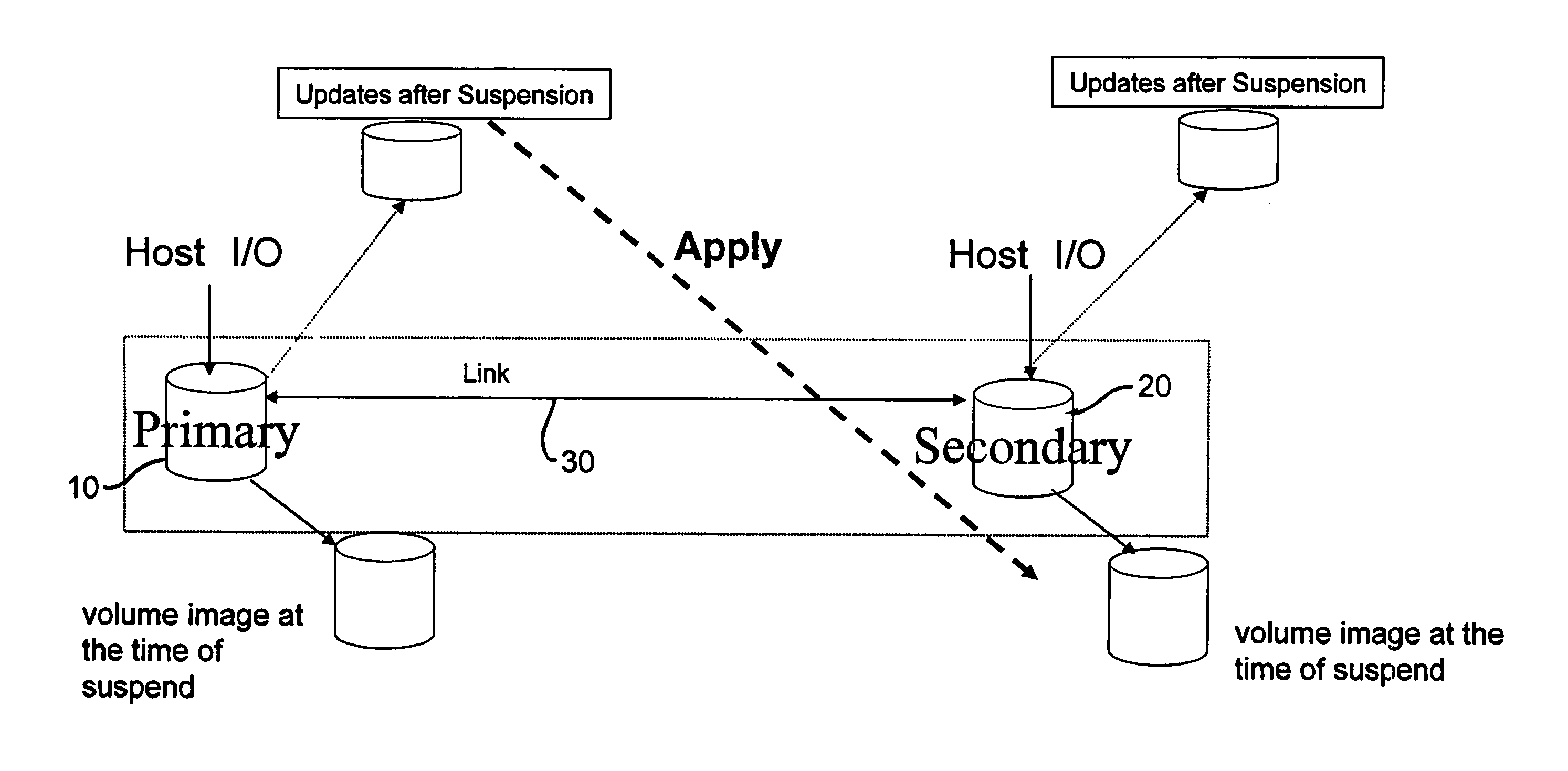
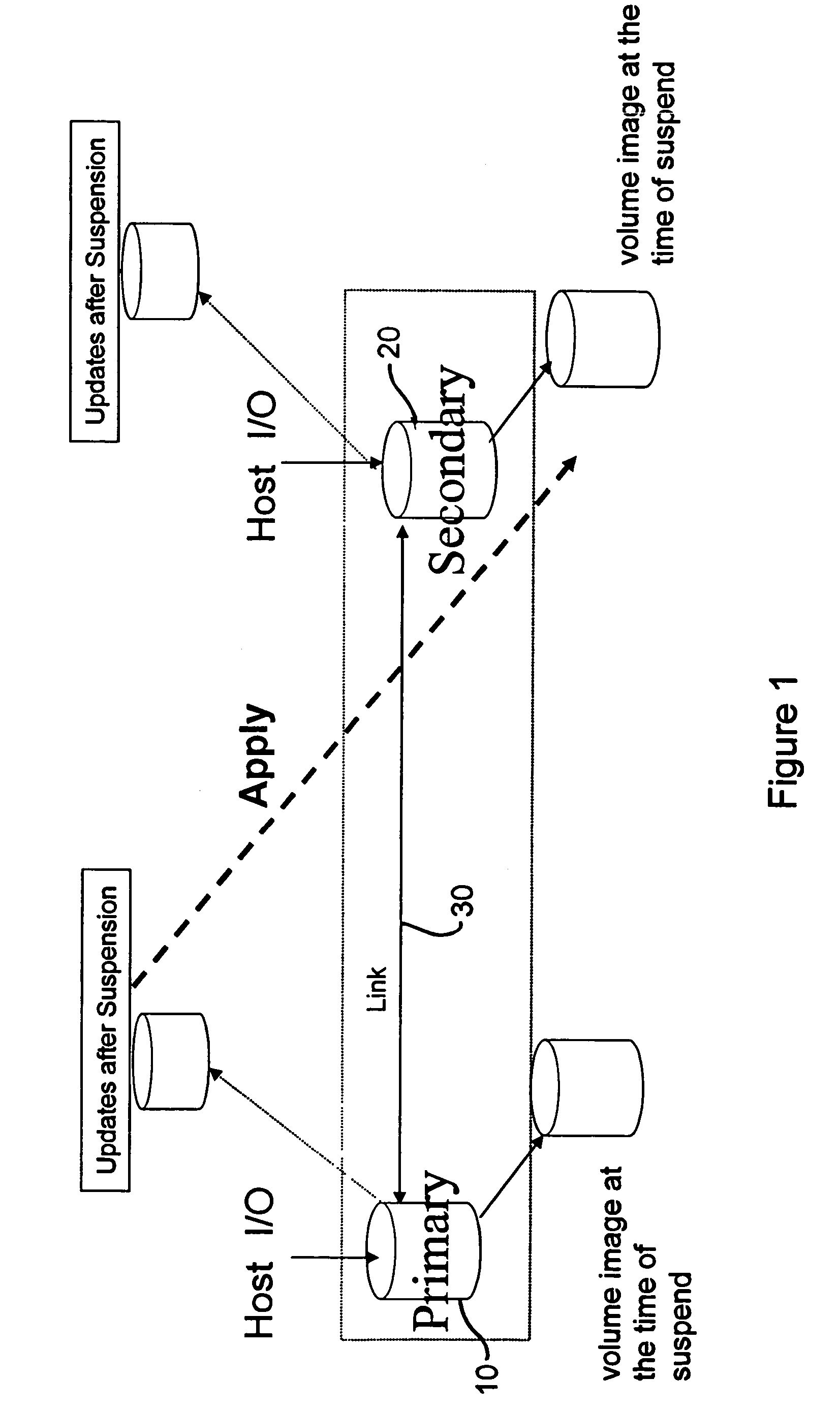
[0024]FIG. 1 is a diagram illustrating an overall configuration for resynchronization of suspended paired volumes. Shown in FIG. 1 are a primary volume 10 and a secondary volume 20 coupled by a link 30. Volumes 10 and 20 will typically be hard disk drives or storage systems containing numerous hard disk drives, while link 30 is provided by any conventional data transfer path, e.g. FibreChannel, the internet, etc. For typical remote replication functionality, link 30 will typically be a link between the two storage systems such as FibreChannel, ESCON, Ethernet, ATM, Sonet, etc. In addition, the link may also be provided by data transfer logic and receiver logic for temporarily stored data, for example in a cache memory or a buffer memory. As will be apparent, the exact implementation for the link 30 is not significant with respect to a conceptual level understanding of the invention described below.

[0025]Volumes 10 and 20 are typically configured as primary (P) and secondary (S) volu...


PUM


Abstract

A technique for restoring data after suspension of a communications link between two storage systems is disclosed. Upon suspension of the link, an image of the data at the first and second locations is created in a secure location. While the link is down, updates to the data at each of the first and second locations are maintained separately. Upon reestablishment of a communications link, the two locations are again synchronized.

Description

BACKGROUND OF THE INVENTION[0001]This invention relates to systems for storing data, and in particular to volume replication in storage area networks. Large storage systems are now well known in which primary and secondary storage systems are provided for a data center or other similar need. The primary and secondary volumes are sometimes also referred to as production and replica volumes, respectively. In such storage systems the primary and secondary storage systems (or subsystems) are linked, for example, using a communications link such as an optical fiber, the Internet, or other well known data communication pathway. The purpose of linking such systems is to assure that an extra copy of data is available at a remote location. This assures that a natural disaster, a failure of the data link, a failure of one or the other storage systems, or other event, does not preclude the system from having useful data.[0002]The volume replication function has become popular as a fundamental ...

Claims


Application Information

Patent Timeline
Patent Type & Authority Patents(United States)
IPC IPC(8): G06F11/00G06F12/00
CPCG06F11/2082
Inventor FUJIBAYASHI, AKIRA
Owner HITACHI LTD
Why Eureka
Try Eureka