Gate

a technology for gates and doors, applied in the field of gates, can solve the problems of children or pets not being able to enter a restricted area, and the gate door is not easy to unlatch

Inactive Publication Date: 2006-12-26
CHENG SHU CHEN
View PDF4 Cites 64 Cited by
  • Summary
  • Abstract
  • Description
  • Claims
  • Application Information

AI Technical Summary

Benefits of technology

[0011]The primary objective of the present invention is to provide a gate that keep children or pets from getting into specific areas.

Problems solved by technology

The gate door is not easy to unlatch so children or pets are not able to get into a restricted area.

Method used


Image

  • Gate
  • Gate
  • Gate

Examples


Embodiment Construction

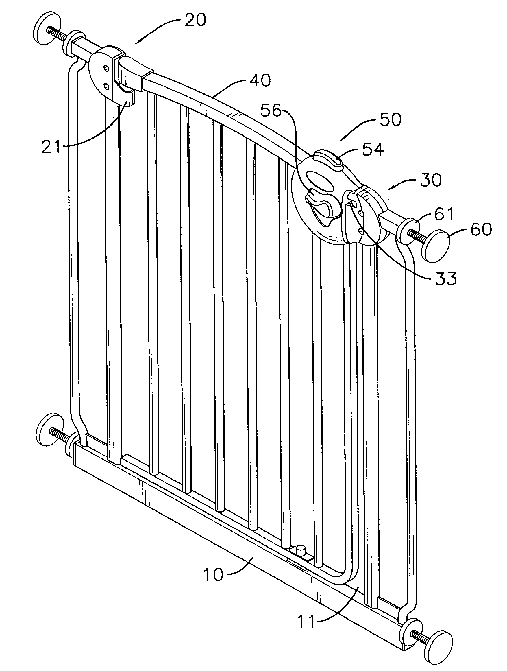
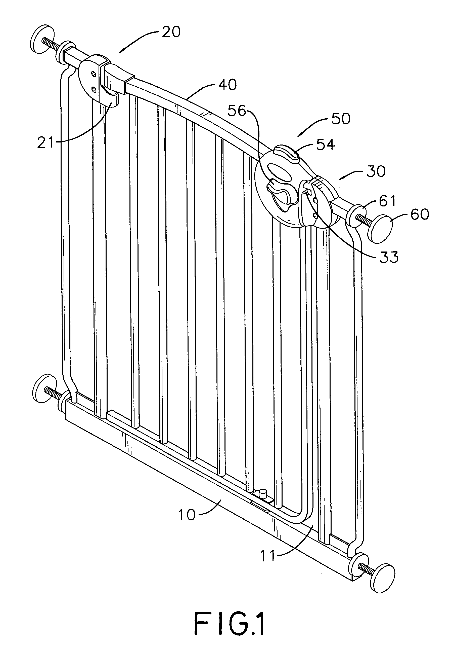
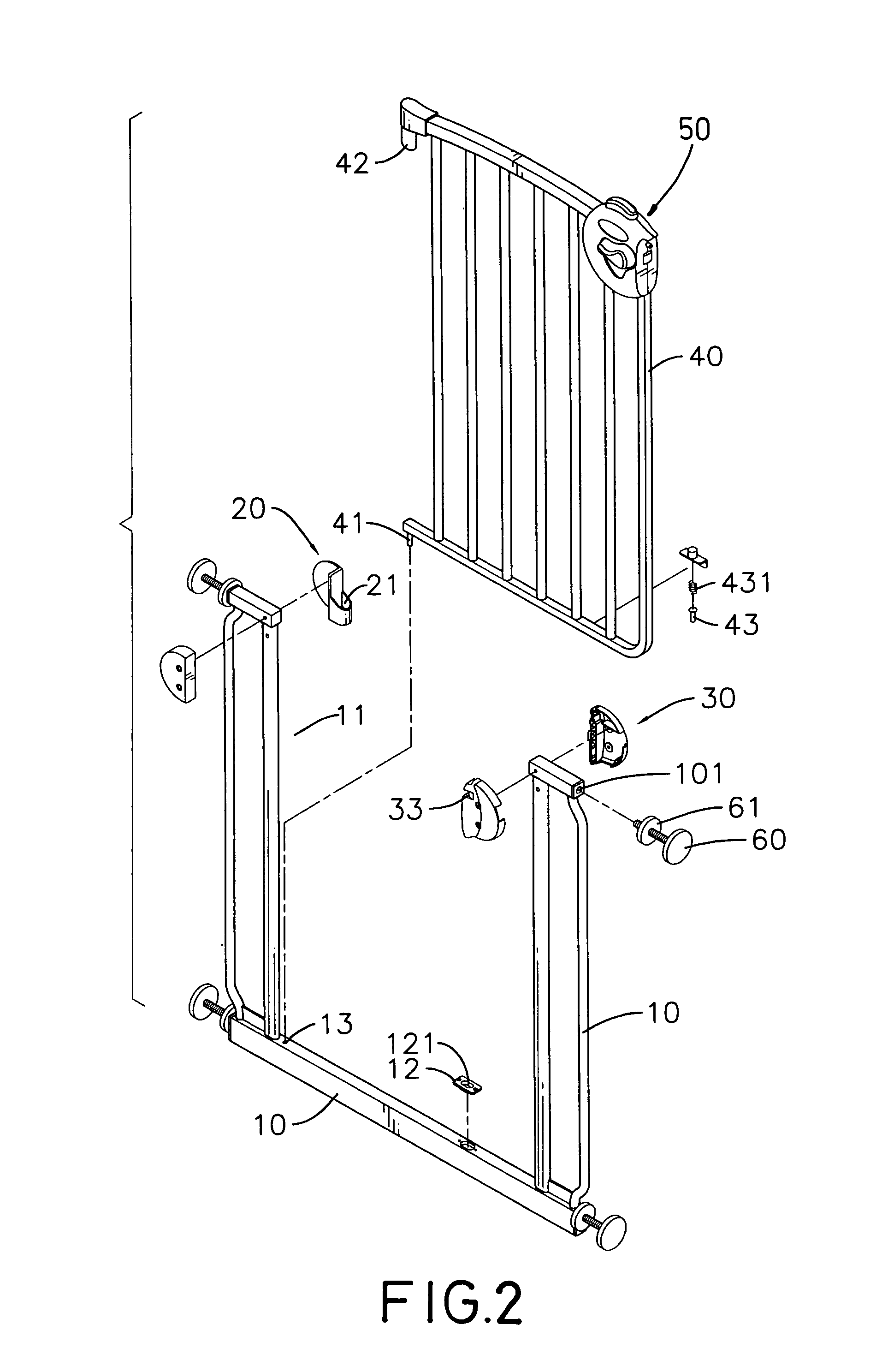
[0026]With reference to FIGS. 1, 2 and 4, a gate in accordance with the present invention comprises a frame (10), a hinge pin seat (20), a latch seat (30), a gate door (40), a latch (50) and four mounting bolts (60).

[0027]The frame (10) has four outer corners, an opening (11), a top inner proximal corner and a top inner distal corner. Each outer corner has a threaded hole (101). The opening (11) is formed in the frame (10) and has a bottom edge, a pivot hole (13) and a locking plate (12). The pivot hole (13) is formed in the bottom edge of the opening (11). The locking plate (12) is mounted on the bottom edge of the opening (11) and has a locking bolt hole (121) formed in the locking plate (12).

[0028]The hinge pin seat (20) is attached to the top inner proximal corner of the frame (10) and has a barrel (21). The barrel (21) is formed in the hinge pin seat (20) and has an inclined inner end.

[0029]With further reference to FIG. 6, the latch seat (30) is attached to the top inner dista...


PUM


Abstract

A gate has a frame, a gate door, a latch and a latch seat. The gate door is pivotally mounted in the frame. The latch is attached to a top corner of the gate door. The latch seat is attached to a top inner corner of the frame. The latch seat and the latch engage each other to latch the gate door to the frame. Unlatching the gate door requires multiple actions so children or pets are not able to open the gate. The safety of children is assured, and pets will not ruin objects isolated by the gate.

Description

BACKGROUND OF THE INVENTION[0001]1. Field of the Invention[0002]The present invention relates to a gate, and more particularly to a gate that keeps children or pets out of restricted areas that may cause injury to children or allow pets to ruin objects in the area.[0003]2. Description of Related Art[0004]Virtually all children and young pets are very active and curious so parents and pet owners have to be vigilant and pay nearly constant attention to keep children from being injured or pets from ruining furniture or household objects.[0005]With reference to FIG. 12, a conventional gate comprises a frame (70), a gate door (71) and a latch (72). The frame (70) is U-shaped and has four outer corners, two proximal inner corners, four holes (701) and four mounting bolts (73). The holes (701) are formed respectively at the outer corners. Each mounting bolt (73) has a threaded shaft, a proximal end, a distal end and a threaded collar (731). The proximal end of the bolt (73) extends into th...

Claims


Application Information

Patent Timeline
Patent Type & Authority Patents(United States)
IPC IPC(8): E05C21/02
CPCE05B65/0014E05C1/06E06B9/04E05B1/0046E05B15/101E05B63/0004E06B2009/002
Inventor CHENG, SHU-CHEN
Owner CHENG SHU CHEN
Why Eureka
Try Eureka