
System operating unit

a technology of operating unit and operating unit, applied in the direction of machine supports, material strength using steady bending force, domestic objects, etc., can solve problems such as operation problems

Inactive Publication Date: 2006-12-26
LEICA MICROSYSTEMS SEMICON GMBH
View PDF15 Cites 92 Cited by
  • Summary
  • Abstract
  • Description
  • Claims
  • Application Information

AI Technical Summary

Benefits of technology

[0016]It is advantageous if the system unit is associated with a system housing. This refers, in particular, to system housings of devices for wafer inspection or for the inspection of semiconductor substrates. Provided on the system housing are two attachment points that are embodied in such a way that a variable arrangement of a system operating unit is possible.
[0021]For use in clean rooms, it is advantageous if the cables that are used to connect the keyboard and monitor to the system are guided in cable conduits. To achieve this, the column is preferably embodied as a cable conduit that comprises a series of openings in order to direct the cables into the interior of the column. To achieve a positively fitting connection to the system housing, the supports are likewise equipped with a cable conduit, which is embodied in such a way that the cables can be guided through the column into the cable conduits of the supports, from which they are directed into the interior of the system housing.
[0023]A further constituent of the present invention is a system housing, in particular for an inspection device, which is embodied so as to make possible single-sided attachment of the above-described system operating unit at at least two points on the housing. In the preferred embodiment, corresponding orifices with threads and cable inlets are made available at two corners of the system housing. Also provided are plug connections which allow the end user to mount the operating unit in variable fashion with no need to accept functional limitations.

Problems solved by technology

Clean rooms, in particular, are often dimensioned in terms of their area in such a way that an unfavorable arrangement of the monitor and keyboard can lead to operating problems.

Method used


Image

  • System operating unit
  • System operating unit
  • System operating unit

Examples


Embodiment Construction

[0029]Numerous modifications and refinements of the exemplary embodiments described can be effected within the context of the invention.

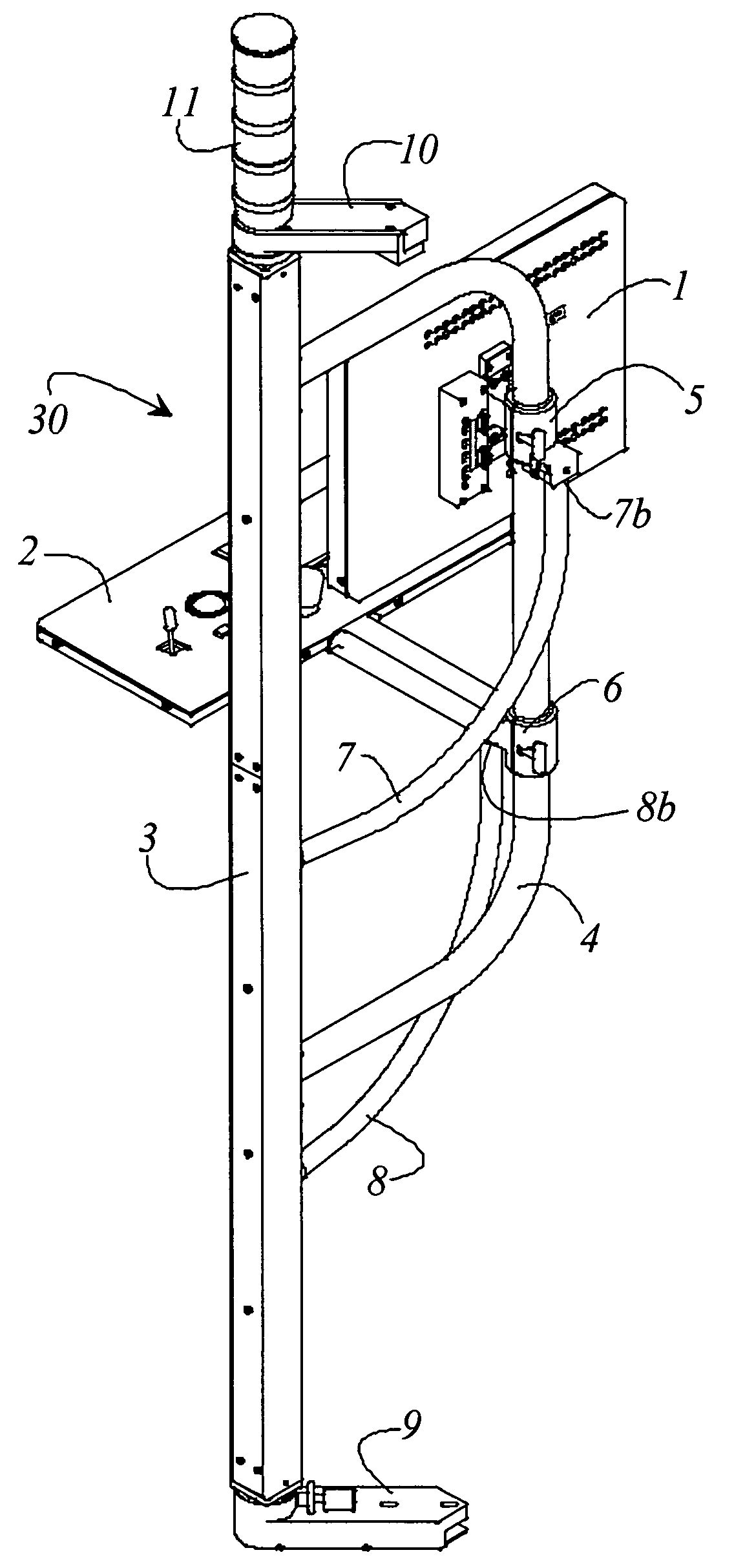
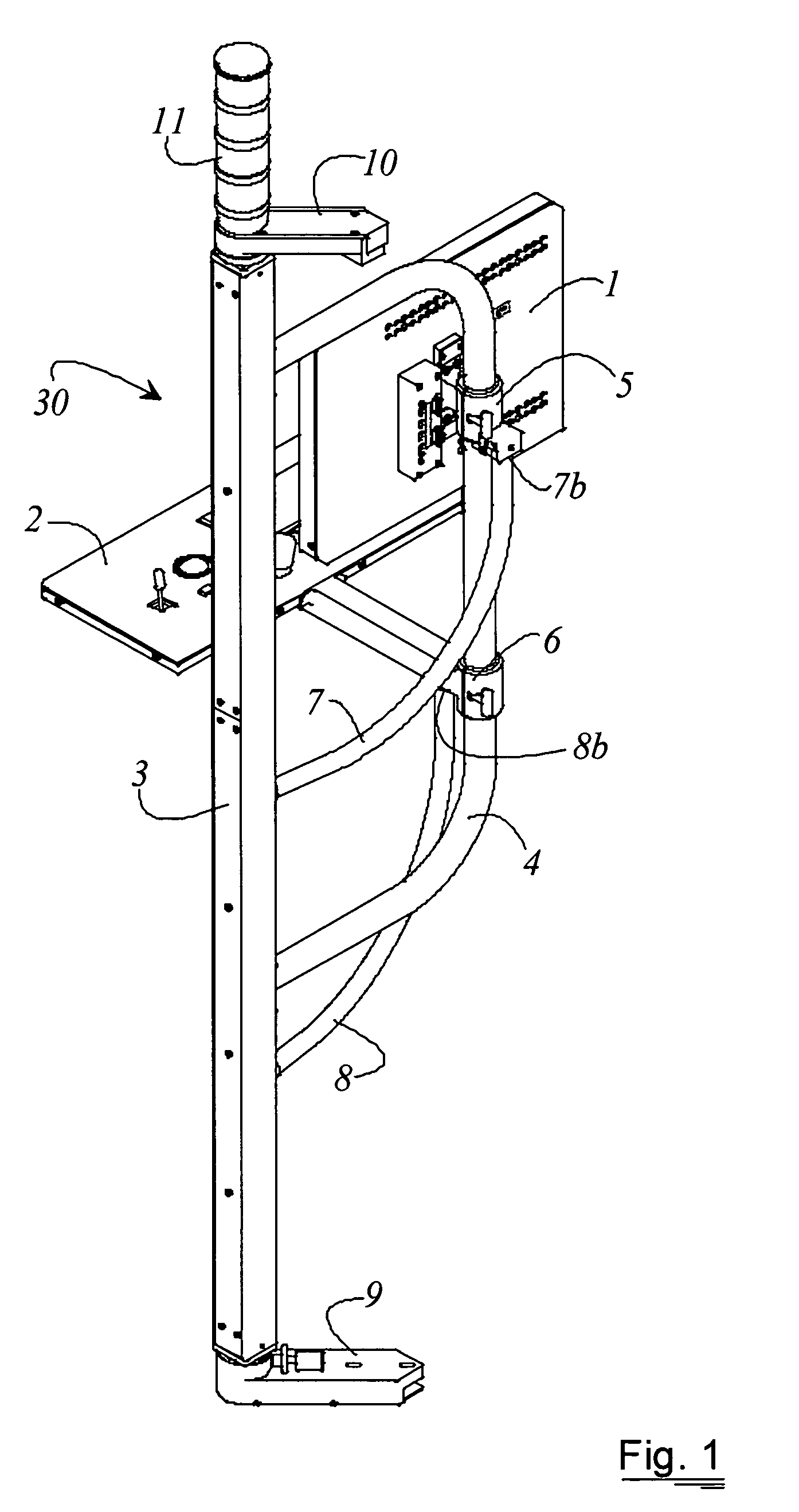
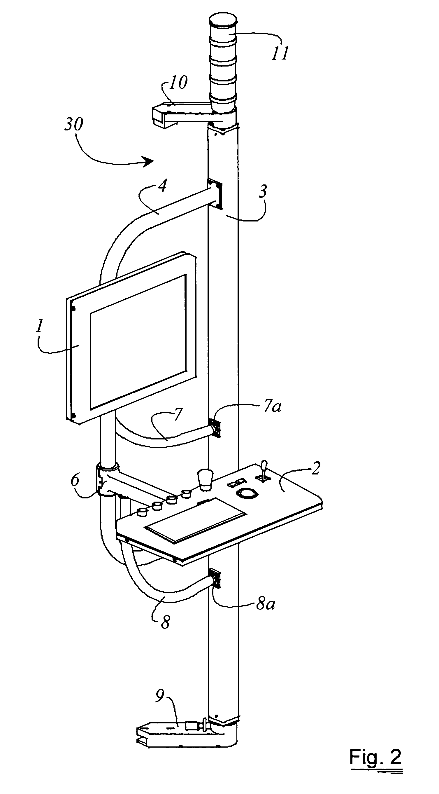
[0030]FIGS. 1 and 2 show the operating unit according to the present invention without a specific attachment to a system housing. A retaining bracket 4 that is U-shaped is attached to a column 3. The two ends of retaining bracket 4 are bolted to column 3. In an alternative embodiment, one or more joints can be arranged between the column and the bracket, allowing a deflection in the horizontal plane. The column is box-shaped and has one side that can be opened, thus allowing access to the cables that are routed inside the column. This embodiment makes it possible for column 3 to be used as a cable conduit 15.

[0031]Arranged at both ends of the column are joints that are connected on the one hand to the end region of column 3 and on the other hand to supports 9, 10.

[0032]Supports 9, 10 are embodied in such a way that they can be used for attachment to...


PUM


Abstract

The invention concerns a system operating unit (30) having a column (3) that is attachable by way of at least two supports (9, 10) to different points of a system housing (14). In the preferred embodiment, this column is attached laterally to the housing, the supports serving for attachment to the housing of the system. In addition, a retaining bracket (4) is connected to the column (3) in such a way that a horizontal deflection of the retaining bracket (4) about a vertical axis is possible.

Description

CROSS REFERENCE TO RELATED APPLICATIONS[0001]This application claims priority of the German patent application 103 25 225.8 which is incorporated by reference herein.FIELD OF THE INVENTION[0002]The invention concerns a system operating unit for inspection devices. The invention refers in particular to a variable attachable system operating unit that is used to control devices for wafer inspection.BACKGROUND OF THE INVENTION[0003]The systems used for wafer inspection often comprise an integrated monitor and an associated keyboard, which are integrated directly into the housing or can be pulled out of the housing using drawers. Clean rooms, in particular, are often dimensioned in terms of their area in such a way that an unfavorable arrangement of the monitor and keyboard can lead to operating problems.[0004]U.S. Pat. No. 6,520,727 discloses an operating device in the form of a monitor that is attached to the frame of the apparatus by means of a retaining arm. The retaining arm is piv...

Claims


Application Information

Patent Timeline
IPC IPC(8): G01N3/20F16M11/00F16M13/02H01L21/00
CPCF16M11/00F16M11/08F16M11/24F16M13/02H01L21/67242
Inventor HEDRICH, ROLANDURBAN, KARSTENWIENECKE, JOACHIM
Owner LEICA MICROSYSTEMS SEMICON GMBH
Learn More