Method of manufacturing a magnetic head and magnetic head manufacturing apparatus

a manufacturing method and technology of a manufacturing apparatus, applied in the manufacture of head surfaces, mechanical control devices, instruments, etc., can solve the problems of defects in the slider are discovered after hsa, and the manufacturing method of the conventional magnetic head is described above. , to achieve the effect of preventing esd and the like damage to elements within the slider, increasing the precision of the standard, and reliably detecting

Inactive Publication Date: 2008-02-26
SAE MAGNETICS H K LTD 50
View PDF4 Cites 1 Cited by
  • Summary
  • Abstract
  • Description
  • Claims
  • Application Information

AI Technical Summary

Benefits of technology

[0016]In further aspect of the magnetic head manufacturing apparatus, the first camera is preferably a ultraviolet (UV) light detecting camera that photographs UV light from a UV light source that reflects from the slider, and bevel portions are preferably formed in edge portions of the pressing surfaces, decreasing the reflectivity of the block members disposed on both sides of the bevel portions, and the slider.
[0017]According to the configuration described above, after disposing a slider on a holding table by using a gripping mechanism, for example, so that an ABS side of the slider becomes an upper surface, a first camera photographs the ABS side of the slider. The ABS and an engraved region are then identified from a photographed image by using an image processing means. In general, the ABS is a smooth surface due to polishing, while on the other hand, the engraved region has a rough surface due to ion milling. Consequently, the engraved region and the ABS can be easily identified from the image provided that binarization processing or the like is performed based on a difference in the amount of light reflected from the engraved region and the ABS when photographing. After processing is performed and different regions are identified, the gripping mechanism again grips the slider from the holding table, and a reference point in a suspension attachment surface (in other words, an attachment position to the suspension) is computed from the different regions and from an image from a second camera by using a coordinate computing means.
[0019]After the adhesive is discharged to the position computed from a standard surface of the suspension attachment surface, the gripping mechanism again moves the slider to a distal end of the suspension along a slider conveying pathway. It then becomes possible to attach the slider to the distal end of the suspension provided that the gripping mechanism is moved downward. The orientation of the slider is thus set so that the ABS is on the upper side, and the slider can be moved along the conveying pathway in a state where a fixed orientation is maintained. Accordingly, complex operations and complex processes for inverting the orientation are unnecessary, and damage to elements within the slider due to ESD and the like can be prevented.
[0020]It should be noted that a step between the ABS and the engraved region that is difficult to detect by using visible light can be reliably detected provided that ultraviolet light (UV light) is irradiated to the ABS and the engraved region, and reflected light is captured by a UV light detecting camera, because UV light has a shorter wavelength than visible light. Accordingly, the ABS and the engraved region can be reliably identified provided that UV light irradiation is performed and that the UV light detecting camera captures the reflected light. It thus becomes possible to increase the precision of the standard.
[0021]Further, the reflectivity of light in the periphery of the slider decreases with respect to the rear surface of the slider provided that bevels are formed in edge portions of pressing surfaces of the gripping mechanism. Consequently, contours of the slider become clearer, and the external shape of the slider can be reliably ascertained by image recognition, provided that the beveled edge portions and the use of UV light are combined.
[0022]According to the present invention, there is provided a method of manufacturing a magnetic head for attaching a slider, on which an air bearing surface (ABS) is formed, onto a suspension. In this method, an upper side surface on which the ABS is formed is photographed together with an outer shape of the slider. The ABS and an engraved region formed within the ABS are next identified from a photographed image, and a reference that is an attachment guide for the suspension are computed. A positional relationship between the reference and the outer shape of the slider is then stored as association information. The outer shape of the slider is then measured, the measured value is compared with the association information, and the reference is read out when attaching the slider to the suspension. An adhesive is discharged, from below, to a suspension attachment surface on the slider, based on the reference. Attachment of the slider to the suspension is then performed while maintaining a state where the ABS is positioned on the upper side. Alternatively, there is provided a magnetic head manufacturing apparatus, in which the slider on which the ABS is formed is attached to the suspension. In this apparatus, a first camera that is disposed above the slider and that photographs the surface on which the ABS is formed and the outer shape of the slider, a second camera that is disposed below the slider and that photographs the outer shape of the slider, an adhesive discharging means that is capable of dispensing an adhesive onto the suspension attachment surface of the slider from below, and the suspension in a state where the ABS is positioned on the upper side, maintaining an orientation so that attachment of the slider is possible, are disposed in sequence on a conveying pathway of the slider. A gripping mechanism made from two block structure members, where the two block members are capable of sliding with respect to each other and where a pressing surface is formed on each of the two block members, is moveably provided along the conveying pathway. A horizontal regulating surface that contacts the ABS of the slider is formed on one of the block members. One image processing means that identifies the ABS, and the engraved region formed within the ABS, from the image photographed by the first camera, and another image processing means that computes a reference, which becomes a guide for attaching the suspension, from identification information from the one image processing means and from the second camera, and then stores a positional relationship between the reference and the outer shape of the slider as association information, are connected to the adhesive discharging means and the gripping means. Accordingly, it becomes possible to post mount a slider to a distal end of a suspension without inverting the orientation of the slider, and damage to elements within the slider due to ESD and the like can be prevented.

Problems solved by technology

However, problems like those described below exist with the conventional magnetic head manufacturing methods described above.
A danger thus exists that elements within the slider will be damaged due to electrostatic discharge (ESD) or the like.
When a non-defective slider at the HGA assembly state becomes defective during processing, the defects in the slider are discovered after HSA assembly.
Finished product yield consequently decreases, and there are cost increases.
With a method in which attachment of the slider is performed from a vertical direction by using a conventional suction nozzle, there is a problem in that the suction nozzle interferes with the other facing suspension, and the slider thus cannot be attached.
Consequently, an adhesive cannot be applied by a conventionally used syringe or needle.
However, operations to invert the slider lead to a manufacturing apparatus become complex, and the amount of slider handling operations increases.
Consequently a risk that elements within the slider will be damaged due to ESD becomes greater.

Method used


Image

  • Method of manufacturing a magnetic head and magnetic head manufacturing apparatus
  • Method of manufacturing a magnetic head and magnetic head manufacturing apparatus
  • Method of manufacturing a magnetic head and magnetic head manufacturing apparatus

Examples


Embodiment Construction

[0029]Preferred specific embodiments of a method of manufacturing a magnetic head, and a magnetic head manufacturing apparatus, according to the present invention are explained in detail below with reference to the appended drawings.

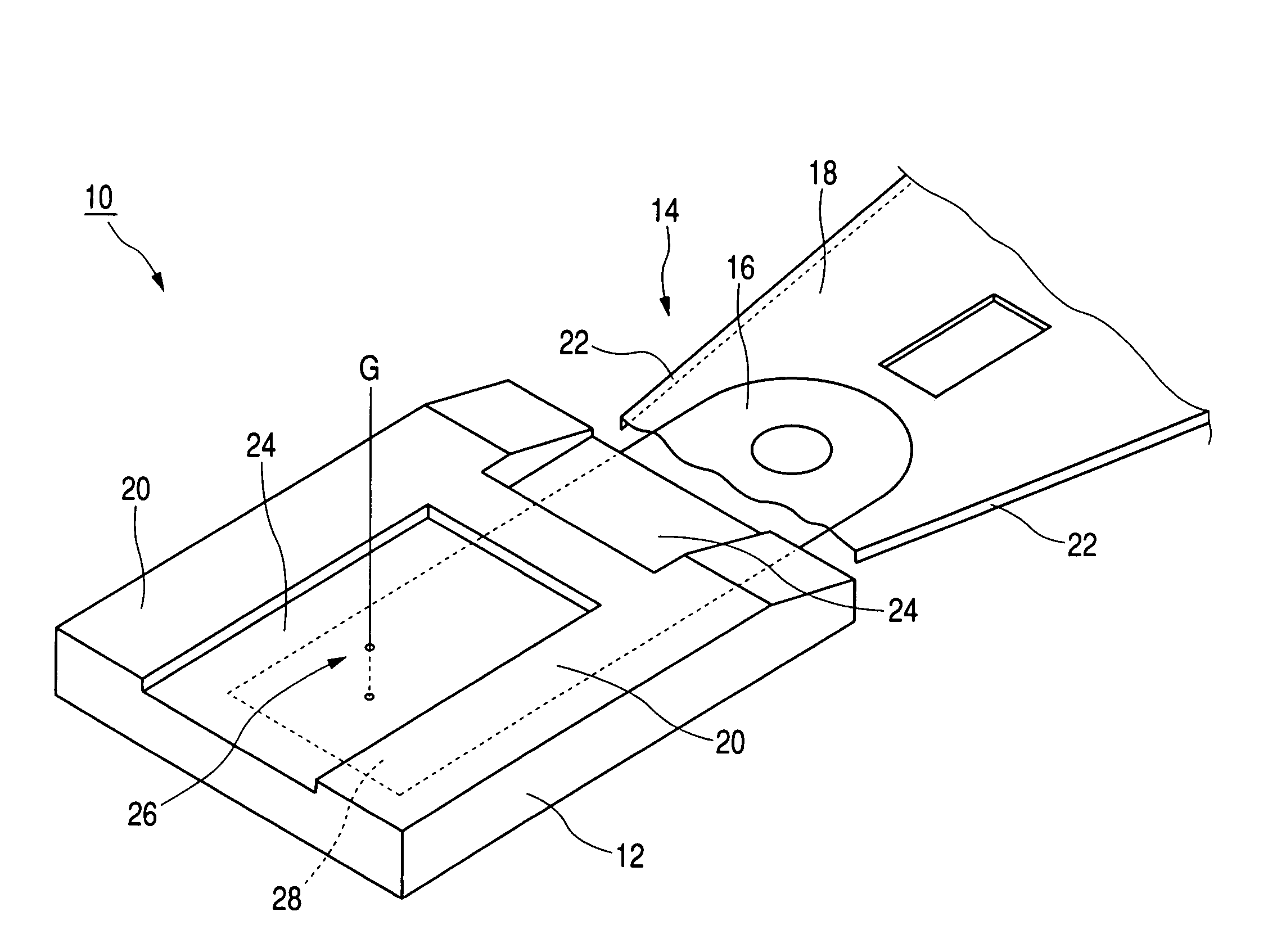
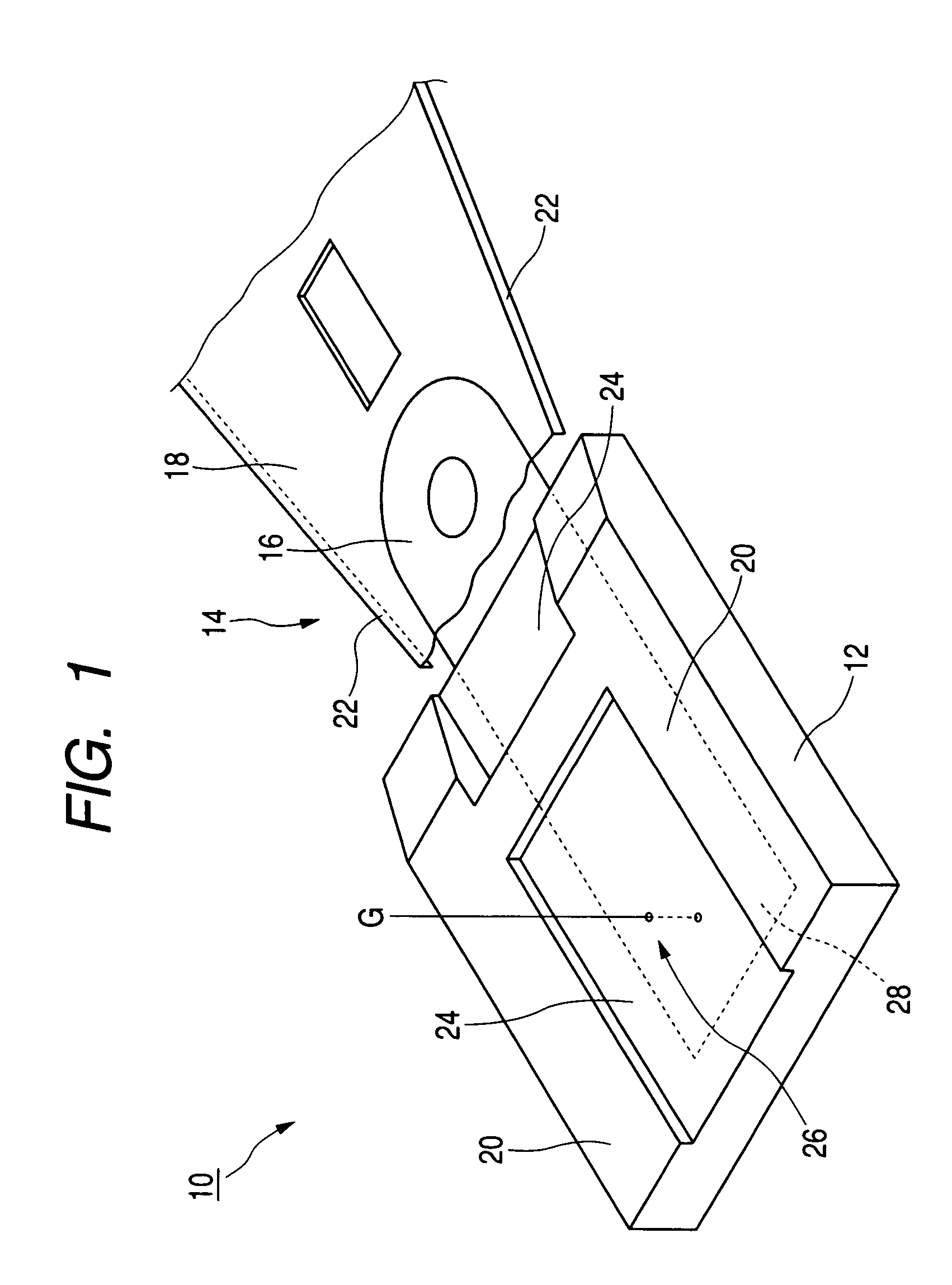
[0030]FIG. 1 is a perspective view of a magnetic head manufactured by using a method of manufacturing a magnetic head according to an embodiment of the present invention. Referring to FIG. 1, a magnetic head 10 that is manufactured by using the method of manufacturing a magnetic head according to this embodiment includes a slider 12 in which a giant magneto-resistive (GMR) element is incorporated, and a suspension 14 that is fixed to the slider 12. The suspension 14 includes a flexure 16 that is bonded and fixed to the slider 12, a load beam 18 that is connected to the flexure 16 by spot welding, and a flexible printed circuit (FPC, not shown) that provides wirings for the GMR element that is formed on the slider 12.

[0031]An ABS 20 is formed on a side of...


PUM

PropertyMeasurementUnit
shapeaaaaaaaaaa
surface areaaaaaaaaaaa
defectsaaaaaaaaaa

Abstract

After photographing a surface on which an ABS is formed, and the outer shape of a slider, the ABS and an engraved region formed within the ABS are identified from a photographed image. A reference that becomes a guide for attaching to a suspension is then computed, and a positional relationship between the reference and the outer shape of the slider is stored as association information. Next, the outer shape of the slider is measured, and measured values are compared to the association information and a reference is read out when attaching the slider to the suspension. An adhesive is discharged, from below, onto a suspension attachment surface of the slider based on the reference. The slider may then be attached to the suspension while holding the slider in a state where the ABS is positioned on an upper side of the slider.

Description

BACKGROUND OF THE INVENTION[0001]1. Field of the Invention[0002]The present invention relates to a method of manufacturing a magnetic head, and to a magnetic head manufacturing apparatus. In particular, the present invention relates to a method of manufacturing a magnetic head, and to a magnetic head manufacturing apparatus, suitable for post mounting of a slider onto a suspension.[0003]2. Related Background Art[0004]Hard disk drives (hereinafter called HDDs) are increasing in capacity and are being made thinner. Together with these advances, magnetic heads (20%, 30% sliders) are also being made smaller.[0005]When bonding a slider, on which a giant magneto-resistive (GMR) element is formed, to a suspension side with conventional processes of manufacturing magnetic heads, positioning of the slider is performed first using the external shape of the slider as a reference. An adhesive agent is applied to a rear surface side of the slider (side opposite to a side where an air bearing sur...

Claims


Application Information

Patent Timeline
Patent Type & Authority Patents(United States)
IPC IPC(8): B32B41/00G11B5/60G05G15/00G11B5/187G11B21/21
CPCG11B5/187G11B5/6005G11B21/21G11B5/4826
Inventor TAKANUKI, KAZUAKISHINDO, OSAMUNAKAO, AKIMASAYAMAGUCHI, SATOSHI
Owner SAE MAGNETICS H K LTD 50
Why Eureka
Try Eureka