Torque detection device and electric power steering apparatus using the same

a technology of torque detection and electric power steering, which is applied in the direction of electrical steering, transportation and packaging, instruments, etc., can solve the problem of difficult to carry out the task of fixing the torque detection device at an appropriate position in the housing

Active Publication Date: 2011-09-20
JTEKT CORP +1
View PDF19 Cites 3 Cited by
  • Summary
  • Abstract
  • Description
  • Claims
  • Application Information

AI Technical Summary

Benefits of technology

[0014]According to the first aspect, since the attachment-preventing convex part is arranged on one end face in the axis line direction of the holding ring, the attachment-preventing convex part contacts the stationary object thereby preventing attachment to the stationary object when attached to the stationary object in a direction opposite to an appropriate direction. Therefore, attachment to the stationary object in a direction opposite to the appropriate direction is reliably prevented.
[0015]According to the second aspect, attachment to the stationary object becomes possible without taking directivity into consideration since the holding ring is formed symmetric to the axis line direction with the middle in the axis line direction as the center. In this case, the holding ring is directed in one of the two directions, and thus the electrical characteristics of the output signal outputted from the detector become appropriate electrical characteristics or electrical characteristics whose phase on the coordinate axis is the opposite from the appropriate electrical characteristics. Which one is the electrical characteristic is found from the quality inspection after assembling. If the phase of the electrical characteristics of the output signal outputted from the detector is the opposite of the phase of the electrical characteristics of the output signal outputted from the detector when the holding ring is attached in the appropriate direction from the quality inspection, the phase of the electrical characteristics of the output signal outputted from the detector can be corrected by rewriting the set data stored in the memory of the detector.
[0016]According to the third aspect, the attachment-preventing convex part is arranged on one end face in the axis line direction of the holding ring, and thus when the torque detection device is inserted to the pass-through hole of the housing in a direction opposite to the appropriate direction, the attachment-preventing convex part contacts the housing and thus cannot be inserted into the pass-through hole. Therefore, the torque detection device is reliably prevented from being incorporated into the housing in the direction opposite to the appropriate direction.
[0017]Since the holding ring of the torque detection device is formed symmetric to the axis line direction with the middle in the axis line direction as the center, the holding ring of the torque detection device can be inserted to the pass-through hole of the housing without taking directivity into consideration. In this case, the torque detection device is directed in one of the two directions, and thus the electrical characteristics of the output signal outputted from the detector become appropriate electrical characteristics or electrical characteristics whose phase on the coordinate axis is the opposite from the appropriate electrical characteristics. Which one is the electrical characteristic is found from the quality inspection after assembling. If the phase of the electrical characteristics of the output signal outputted from the detector is the opposite of the phase of the electrical characteristics of the output signal outputted from the detector when the holding ring is attached in the appropriate direction from the quality inspection, the phase of the electrical characteristics of the output signal outputted from the detector can be corrected by electrically rewriting the set data stored in the memory of the detector.

Problems solved by technology

However, in the torque detection device configured as in Patent Document 1, the entire torque detection device is inserted to the inside of the housing and fixed inside the housing, and thus the task of fixing the torque detection device at an appropriate position in the housing is difficult to carry out, and improvement is desired.

Method used


Image

  • Torque detection device and electric power steering apparatus using the same
  • Torque detection device and electric power steering apparatus using the same
  • Torque detection device and electric power steering apparatus using the same

Examples


first embodiment

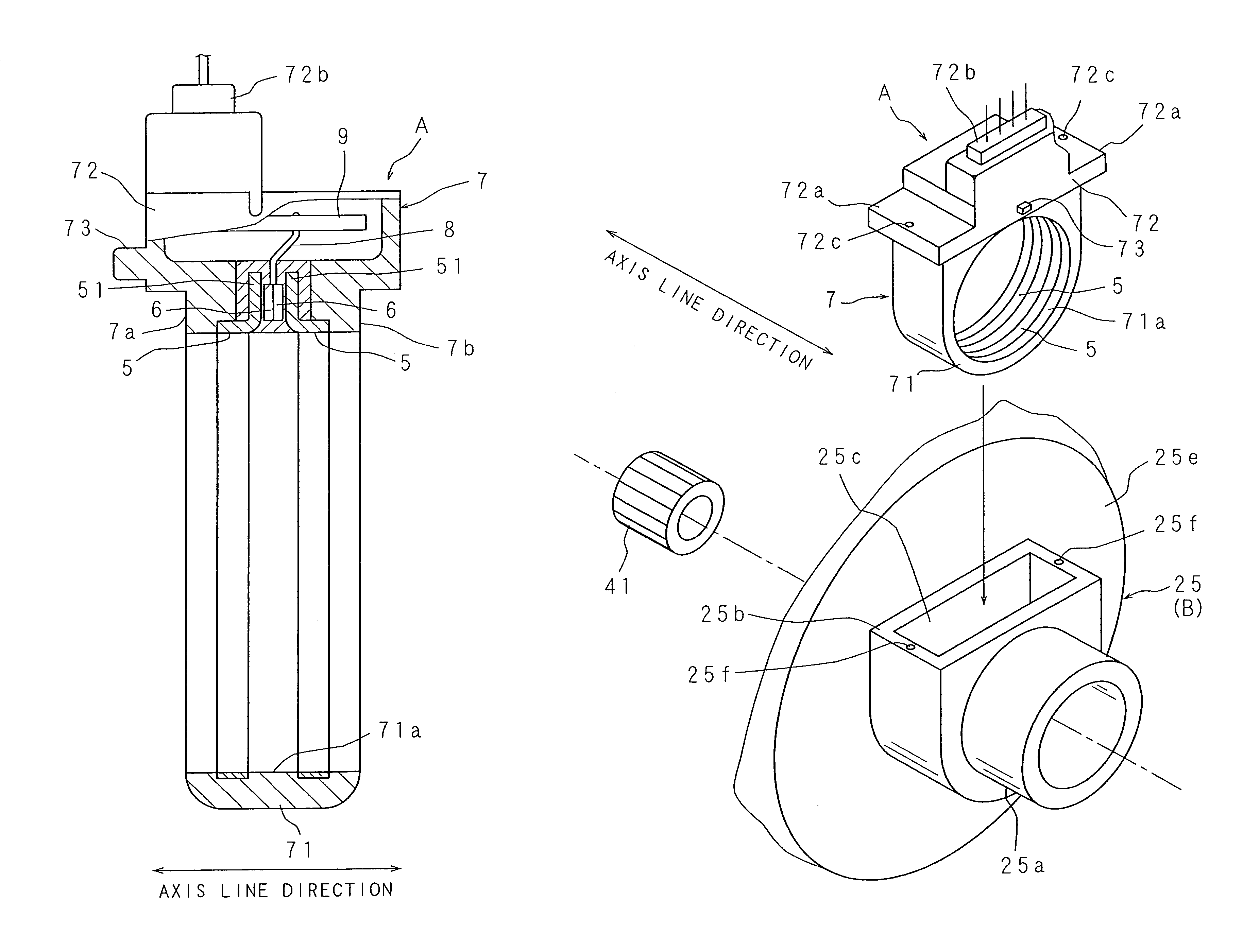
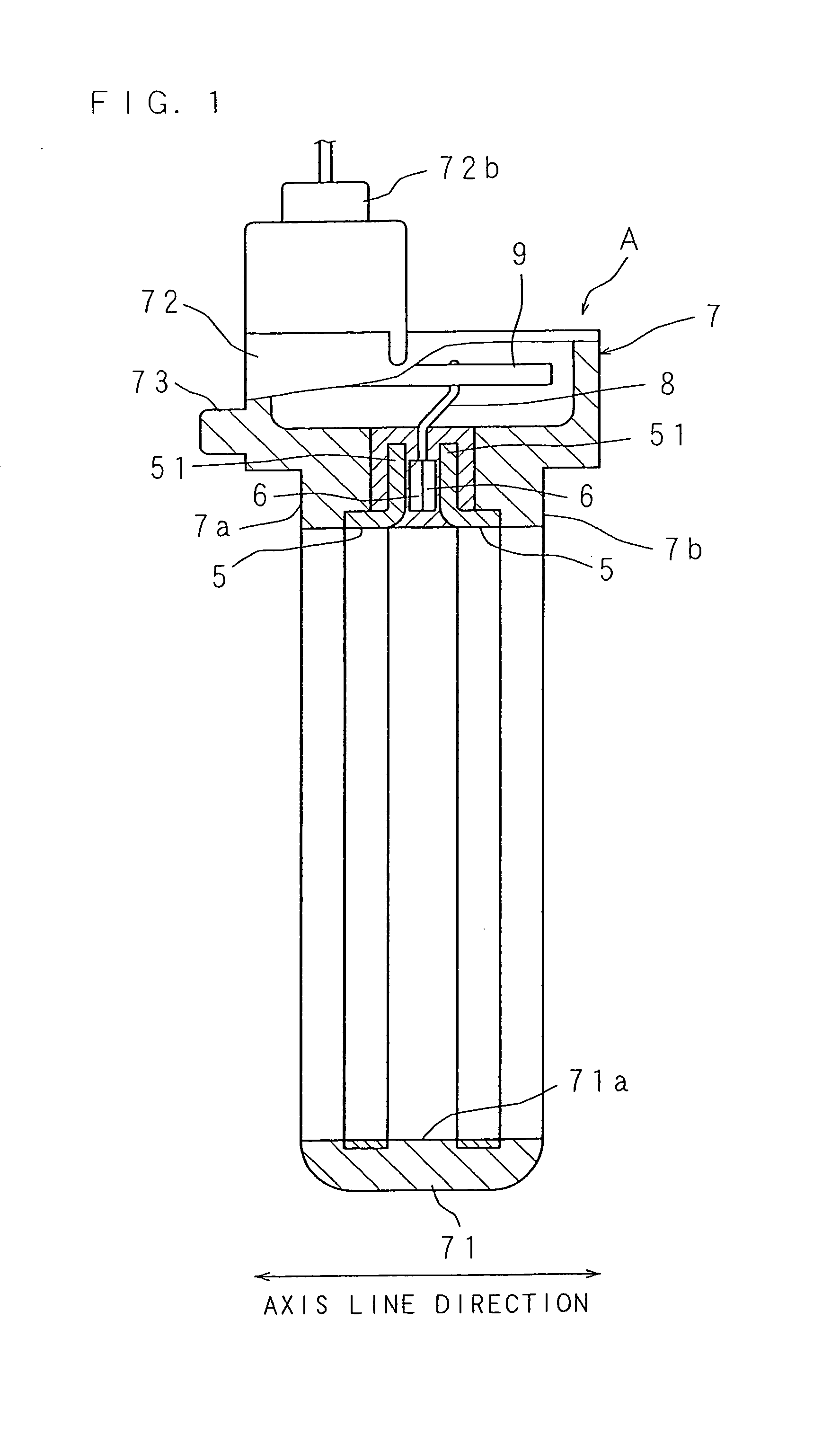
[0050]FIG. 1 is a cross sectional view showing a configuration of a torque detection device according to the present invention, FIG. 2 is a side view showing the configuration of the torque detection device, FIG. 3 is a front view showing the configuration of the torque detection device, FIG. 4 is a frame format exploded perspective view showing the configuration of the torque detection device, and FIG. 5 is an explanatory view of a magnetic circuit formed when a rotating body is rotated in one direction.

[0051]A torque detection device A includes two magnetic flux collecting rings 5, 5, arranged spaced apart in an axis line direction outside the outer periphery of a magnetic circuit forming member 4 of a first rotating body 2 and a second rotating body 3 coaxially coupled by a torsion bar 1, for collecting the magnetic flux generated by the magnetic circuit forming member 4; a detector 6 for detecting the torque applied to the first rotating body 2 based on the density of the magnet...

second embodiment

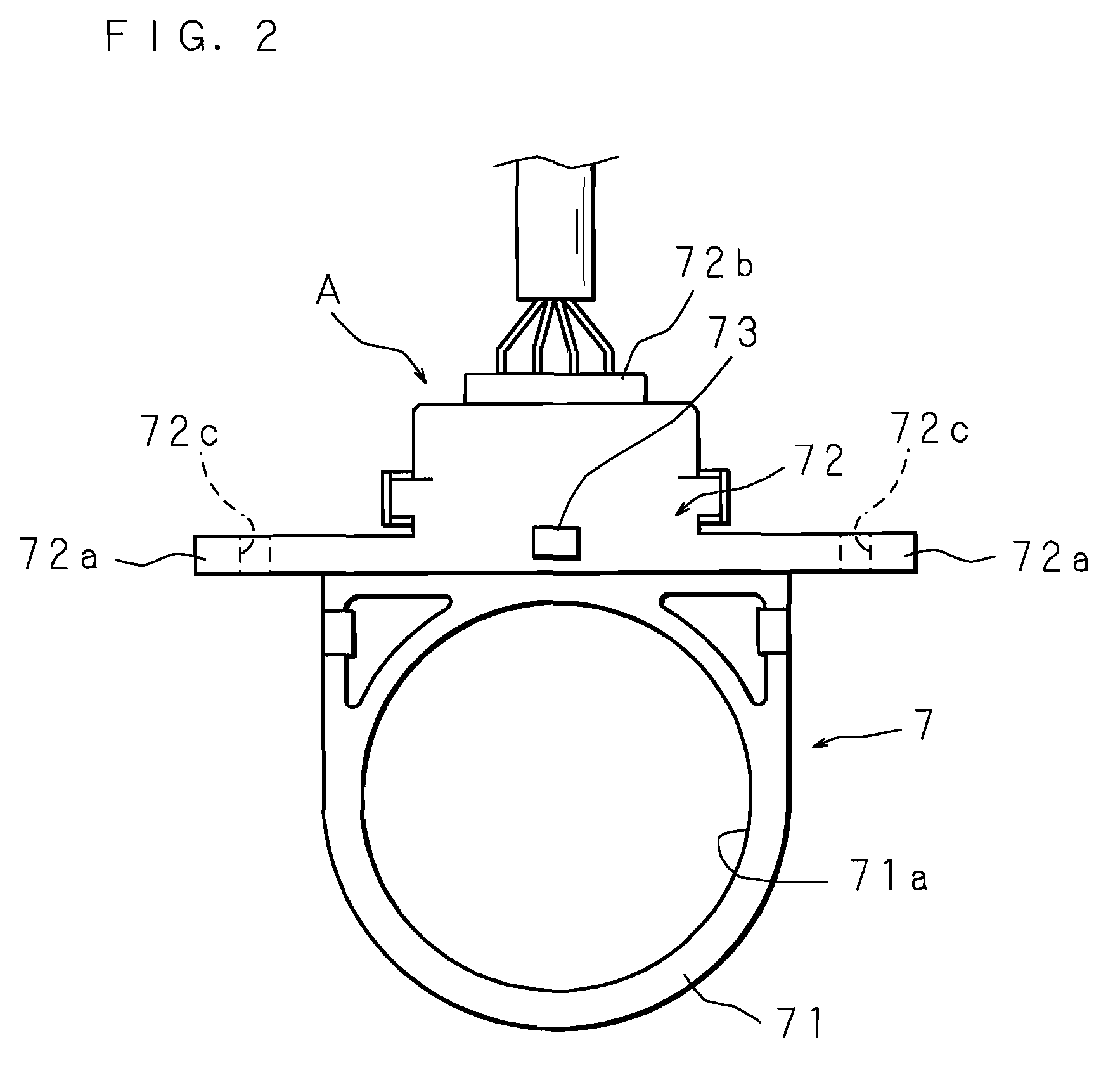
[0066]FIG. 10 is a front view showing a configuration of a second embodiment of the torque detection device, FIG. 11 is a side view, and FIG. 12 is a plan view. In this torque detection device, the attachment-preventing convex part 73 of the first embodiment is omitted, and the conductive wire retrieving part 72b and the insertion holes 72c, 72c are arranged at the middle in the axis line direction of the attachment part 72, so that the holding ring 7 can be incorporated in the housing 25 while being formed symmetric in the axis line direction with the middle X in the axis line direction as the center and without taking directivity into consideration.

[0067]In the second embodiment, the detector 6 is configured by the Hall IC, and includes a magnetic sensitive element and an EEPROM memory.

[0068]FIG. 13 is a plan view of the main parts showing an example of use in the electric power steering apparatus. When incorporating the torque detection device of the second embodiment to the hous...


PUM

PropertyMeasurementUnit
magnetic fluxaaaaaaaaaa
densityaaaaaaaaaa
torqueaaaaaaaaaa

Abstract

A torque detection device has a magnetic flux collecting ring, arranged outside an outer periphery of a magnetic circuit forming member which is provided in a rotating body applied with a torque, for collecting a magnetic flux generated by the magnetic circuit forming member; a detector for detecting the torque applied to the rotating body based on a density of the magnetic flux collected by the magnetic flux collecting ring; and a holding ring for holding the magnetic flux collecting ring and the detector and including an attachment part to be attached to a stationary object on an outer periphery on one side in a radial direction. An attachment-preventing convex part for preventing attachment to the stationary object by contacting the stationary object is formed on one end face in an axis line direction of the holding ring.

Description

CROSS-REFERENCE TO PRIOR APPLICATIONS[0001]This is a U.S. national phase application under 35 U.S.C. §371 of International Patent Application No. PCT / JP2006 / 319135, filed Sep. 27, 2006, and claims the benefit of Japanese Application No. 2005-282310, filed Sep. 28, 2005, both of which are incorporated by reference herein. The International Application was published in Japanese on Apr. 5, 2007 as International Publication No. WO 2007 / 037255 A1 under PCT Article 21(2).TECHNICAL FIELD[0002]The present invention relates to a torque detection device for detecting a torque applied to a rotating body, and an electric power steering apparatus including the torque detection device and a steering assist electric motor.BACKGROUND ART[0003]A torque detection device is disclosed in Patent Document 1 and the like. The torque detection device of Patent Document 1 includes two magnetic flux collecting rings, arranged in a spaced side by side relation in an axis line direction outside an outer periph...

Claims


Application Information

Patent Timeline
Patent Type & Authority Patents(United States)
IPC IPC(8): G01L3/00
CPCB62D6/10G01L3/104
Inventor ISHIHARA, TOSHIHARUTOKUMOTO, YOSHITOMOHAKAMATA, SINJIJOUSHITA, KANAMEHORIUCHI, TOMOHARUYAHATA, NORIYUKINAKANE, NAOKI
Owner JTEKT CORP
Why Eureka
Try Eureka