Mciropump, tube unit, and control unit

Inactive Publication Date: 2008-06-12
SEIKO EPSON CORP
View PDF69 Cites 47 Cited by
  • Summary
  • Abstract
  • Description
  • Claims
  • Application Information

AI Technical Summary

Benefits of technology

[0053]This configuration makes the control unit available in isolation from the remaining components so that the cost reduction can be achieved for the micropump. The control unit can be conf

Problems solved by technology

The problem with such an infusion pump is that the tube varies in internal diameter, and this causes another variation of the quantity of infusion liquid.
Another problem with the infusion pump above is that when a user attaches a new tube to the infusion pump, there is no validation means to see whether the tube is made for attachment to the pump, thereby possibly causing wrong attachment of tube.
When the liquid is drug preparations for medical treatment use, such wrong attachment is never permissible.
This, however, requires replacement all at once of both the infusion pump and the tube being in a piece, and thus a problem of increasing the running cost is expected.
Another problem is that attaching the tube to the peristaltic pump section is difficul

Method used


Image

  • Mciropump, tube unit, and control unit
  • Mciropump, tube unit, and control unit
  • Mciropump, tube unit, and control unit

Examples


first embodiment

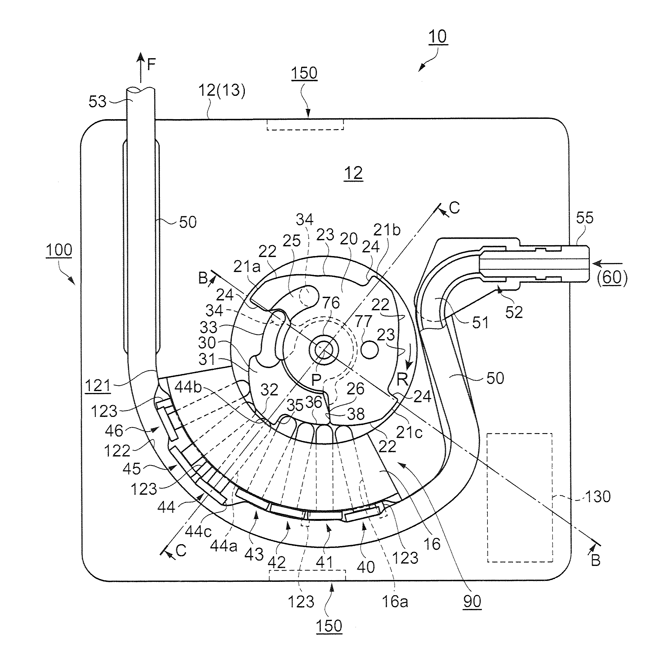
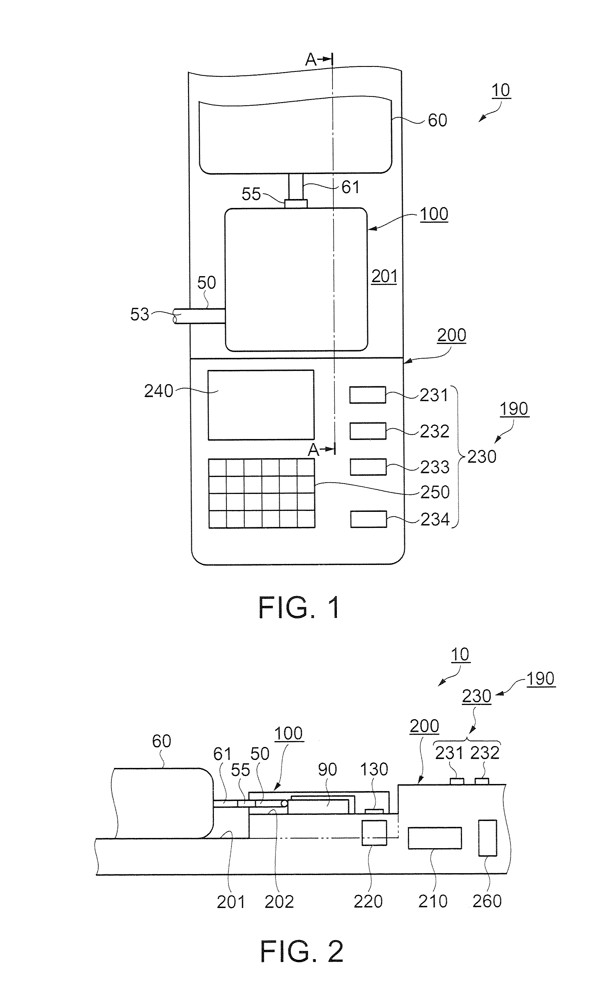
[0073]FIG. 1 is a plan view of a micropump in a first embodiment of the invention, showing the schematic configuration thereof, and FIG. 2 is a cross sectional view of the micropump cut along a line A-A of FIG. 1. In FIGS. 1 and 2, a micropump 10 is configured to include a control unit 200, and a tube unit 100 that is detachably attached to the control unit 200. The tube unit 100 is linked with a reserver 60 via a connection tube 61. The reserver 60 houses therein a fluid, which is described as a liquid in the below.

[0074]The control unit 200 is provided with, on the surface side, a display / operation section 190 and a base 201 for placement thereon of the reserver 60. A part of the base 201 is protruding like a shelf in the thickness direction, and the protruding portion, i.e., a shelf-like section 202, serves as the interface section for the tube unit 100 and the control unit 200. The tube unit 100 is attached to the shelf-like section 202.

[0075]In the tube unit 100, an elastic tub...

second embodiment

[0161]Described next is a micropump in a second embodiment of the invention by referring to the accompanying drawings. In the second embodiment, a tube unit is provided with a depression mechanism section, and the remaining components are almost the same as those in the first embodiment described above. Therefore, described here are only those different from the first embodiment, and any components similar to those in the first embodiment are provided with the same reference numerals.

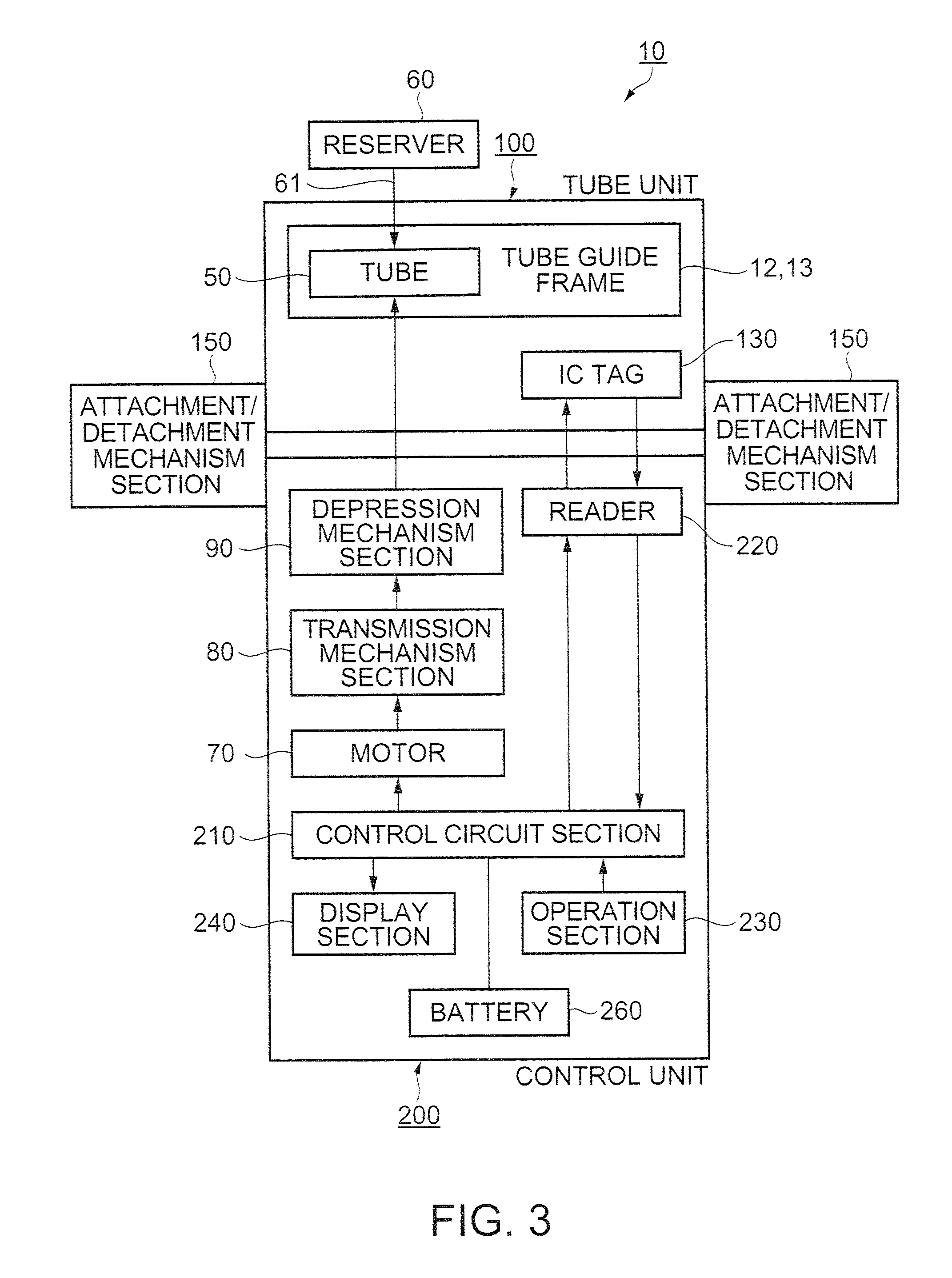
[0162]FIG. 9 is a diagram for illustrating the schematic configuration of the micropump of the second embodiment. In FIG. 9, the micropump 10 is configured by two units, i.e., the tube unit 100 and the control unit 200. These units are driven while being detachably attached to each other by the attachment / detachment mechanism section 150, and discharge a liquid.

[0163]The tube unit 100 is configured to include the tube 50, the tube guide frame, the depression mechanism section 90, and the IC tag 130 serv...

third embodiment

[0173]Described next is a third embodiment of the invention by referring to the accompanying drawings. In the third embodiment, a tube unit is provided with a depression mechanism section, a transfer mechanism section, and a motor. The remaining components are the same as those in the first embodiment described above. Therefore, described here are only those different from the first embodiment, and any components similar to those in the first embodiment are provided with the same reference numerals.

[0174]FIG. 11 is a diagram for illustrating the schematic configuration of a micropump of the third embodiment, and FIG. 12 is a partial cross sectional view of the tube unit and a control unit, showing their relationship. Described first is the configuration of the micropump by referring to FIG. 11. In FIG. 11, the micropump 10 is configured by two units, i.e., the tube unit 100 and the control unit 200. These units are driven while being detachably attached to each other by the attachme...


PUM


Abstract

A micropump of a peristaltic type that continuously transfers a fluid through depression of an elastic tube is disclosed. The micropump includes: a tube unit configured to at least include the tube, a tube guide frame that fixedly holds the tube, and a tube individual data storage section that stores therein tube individual data; a control unit that is attachable/detachable to/from the tube unit, and at least includes a control circuit section that drives and controls, via a transmission mechanism section, a motor for driving a depression mechanism section serving to depress the tube, and a tube individual data processing section that reads the tube individual data for data processing thereof; a power supply that makes an electrical supply to the control unit; and a reader/writer unit that detects attachment of the tube unit to the control unit, and reads the tube individual data for writing to the control unit. In the micropump, the tube individual data is used as a basis for driving.

Description

BACKGROUND[0001]1. Technical Field[0002]The present invention relates to a micropump of a peristaltic type that continuously transfers a fluid through depression of an elastic tube, and a tube unit and a control unit configuring the micropump.[0003]2. Related Art[0004]A previously known infusion pump infuses an infusion liquid filled in a liquid container, i.e., reserver, through depression of a tube. Such an infusion pump is configured to include tube depression means, drive means, and control means. The tube depression means continuously presses and closes a part of the tube, i.e., depression position, in such a manner as to make the infusion liquid to flow in accordance with the set quantity of the infusion liquid. The drive means includes a motor for driving the tube depression means, and the control means is for controlling the drive means. As an example, refer to Patent Document 1 (JP-A-7-59853, p. 3, and FIGS. 1 to 3).[0005]With the infusion pump of Patent Document 1, an elas...

Claims


Application Information

Patent Timeline
IPC IPC(8): F04B43/09F04B43/12
CPCA61M5/14228F04B43/12F04B43/082F04B43/0081
Inventor MIYAZAKI, HAJIMEKAWASUMI, KAZUO
Owner SEIKO EPSON CORP
Why Eureka
Try Eureka