Optoelectrical Connector

a technology of optoelectric connectors and connectors, applied in the field of optoelectric connectors, can solve the problems metal abrasion powder, easy attachment to optical connection parts, etc., and achieve the effect of deteriorating optical coupling efficiency

Active Publication Date: 2012-01-26
JAPAN AVIATION ELECTRONICS IND LTD
View PDF8 Cites 47 Cited by
  • Summary
  • Abstract
  • Description
  • Claims
  • Application Information

AI Technical Summary

Benefits of technology

[0015]In the optoelectrical connector according to the present invention, the shutter is provided on the immediate front of the optical connection part of the receptacle and the shutter is configured to open in the optical connection. Therefore, even if metal abrasion powder is generated by a slide of the electric connection parts of the plug and the receptacle in the electric connection, attachment of the metal abrasion powder to the optical connection part of the receptacle is prevented. On the other hand, the optical connection part of the plug is positioned on the front end of the insertion fitting part and is positioned on a more front side in the insertion direction than the electric connection part, so that the metal abrasion powder hardly attaches to the optical connection part of the plug.
[0016]According to the present invention, such a problem can be cut down that optical coupling efficiency is deteriorated by attachment of the metal abrasion powder, which is generated by the slide of the electric connection parts, to the optical connection parts.

Problems solved by technology

Accordingly, there is a problem that metal abrasion powder which is generated by a slide of metallic terminals in electric connection easily attaches to the optical connection parts.
For example, such situation can be generated that optical coupling efficiency is largely deteriorated by attachment of metal abrasion powder to a lens or the like.
On the other hand, the optical connection part is positioned on a deep side of a space surrounded by the shell in the plug as shown in FIG. 1B, so that it is difficult to clean the optical connection part and even if metal abrasion powder attaches to the optical connection part, the metal abrasion powder cannot be easily removed.

Method used


Image

  • Optoelectrical Connector
  • Optoelectrical Connector
  • Optoelectrical Connector

Examples


Embodiment Construction

[0049]Embodiments of the present invention will be described below.

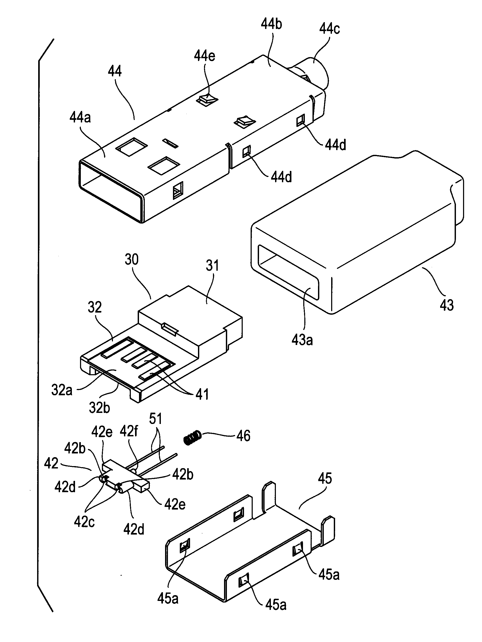
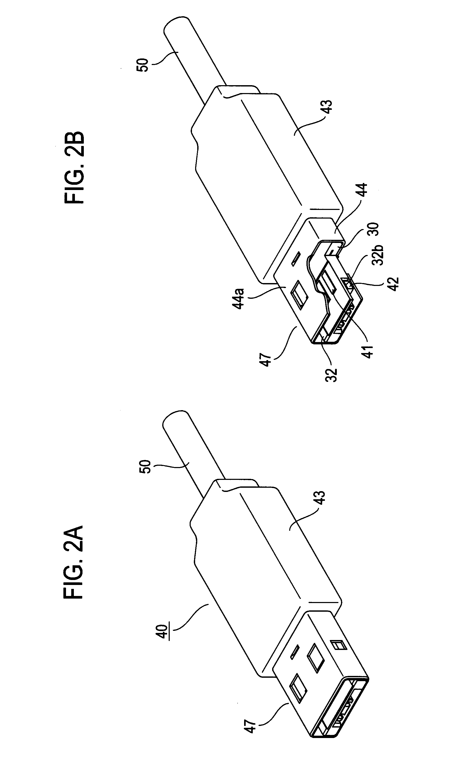
[0050]FIGS. 2A and 2B and FIGS. 3A to 3D illustrate a plug in an optoelectrical connector according to an embodiment of the present invention. FIG. 4 illustrates the plug which is disassembled to respective parts.

[0051]A plug 40 in this example includes an insulation body 30, terminals 41, an optical member 42, a hood 43, and a metallic shell, and the shell is composed of an upper shell 44 and a lower shell 45, as shown in FIG. 4.

[0052]The insulation body 30 includes a base part 31 which has an approximate-parallelepiped shape and a tongue piece 32 which is protruded and extended from a front surface of the base part 31, and is made of resin. A shallow concave part 32a is formed on one plate surface (an upper surface) of the tongue piece 32, and four terminals 41, in this example, constituting an electric connection part are arranged to be disposed on this concave part 32a. The insulation body 30 is shaped such that ...


PUM


Abstract

In an optoelectrical connector that is composed of a plug including an insertion fitting part and a receptacle including a housing space into which the insertion fitting part of the plug is inserted, the plug is provided with an optical connection part (an optical member) on a front end of the insertion fitting part and an electric connection part (terminals) more rearward than the optical connection part. The receptacle is provided with an optical connection part (an optical member) on the deep side of the housing space and an electric connection part (movable contact pieces of terminals) more frontward than the optical connection part. A shutter is formed on the immediate front of the optical connection part of the receptacle and the shutter opens in the optical connection. Deterioration of optical coupling efficiency caused by attachment of metal abrasion powder, which is generated in a slide between the electrical connection parts in the electrical connection, to the optical connection parts, is prevented.

Description

TECHNICAL FIELD[0001]The present invention relates to an optoelectrical connector having both of an optical connecting function and an electrical connecting function.BACKGROUND ART[0002]FIGS. 1A, 1B, and 1C illustrate the configuration of an optoelectrical connector which is disclosed in Japanese Patent Application Laid Open No. 2010-50092, as a prior art example of such kind of optoelectrical connector, which is composed of a plug and a receptacle. FIG. 1A illustrates a plug and FIG. 1B illustrates a plug which is partially disassembled. FIG. 1C illustrates a receptacle.[0003]A plug 10 includes an insulation body 11, plug terminals which are mounted on the insulation body 11, and a metallic shell 12. The insulation body 11 includes a base part 13 which has a fitting surface 13a and a tongue piece 14 which is extended forward from the base part 13. On the base part 13, through holes in which optical fibers are housed are formed, and lenses 15 are disposed so as to be respectively ho...

Claims


Application Information

Patent Timeline
Patent Type & Authority Applications(United States)
IPC IPC(8): G02B6/36
CPCG02B6/322G02B6/3897G02B6/3817
Inventor SHIRATORI, MASAYUKIYAMAUCHI, TAKAYOSHIKAZOU, MITSUAKIAIHARA, SHUICHITORIKAI, TOSHITAKA
Owner JAPAN AVIATION ELECTRONICS IND LTD
Why Eureka
Try Eureka