Method and a device for cleaning of crankcase gas

a technology for cleaning devices and crankcases, which is applied in the direction of machines/engines, centrifuges, separation processes, etc., to achieve the effect of satisfying the cleaning of crankcase gas, reducing rotational speed, and controlling cleaning efficiency and suction efficiency of centrifugal separators

Inactive Publication Date: 2006-12-26
ALFA LAVAL CORP AB
View PDF10 Cites 93 Cited by
  • Summary
  • Abstract
  • Description
  • Claims
  • Application Information

AI Technical Summary

Benefits of technology

[0010]By the invention it is possible to accomplish satisfactory cleaning of crankcase gas from the combustion engine even when the load thereon varies, while a desired gas pressure is maintained in the crankcase of the combustion engine. The invention is based on the understanding that a centrifugal separator that is used need not be operated with the same separation efficiency during the complete operating time of the combustion engine and that the cleaning efficiency and the suction efficiency of the centrifugal separator can be controlled by changing the rotational speed of the centrifugal rotor. Thus, when a relatively small amount of crankcase gas is generated per unit of time, efficient cleaning of the crankcase gas may be accomplished at a substantially lower rotational speed of the centrifugal rotor than is needed when a relatively large amount of crankcase gas is generated per unit of time.
[0011]By use of a centrifugal separator, the centrifugal rotor of which is arranged upon its rotation to suck crankcase gas from the crankcase, the need of an extra pump or fan for transportation of crankcase gas from the crankcase to and through the centrifugal separator is avoided.

Problems solved by technology

This need not always be the case, however, and it is usually not the case when a combustion engine is used for instance for production of electric current.

Method used


Image

  • Method and a device for cleaning of crankcase gas
  • Method and a device for cleaning of crankcase gas
  • Method and a device for cleaning of crankcase gas

Examples


Embodiment Construction

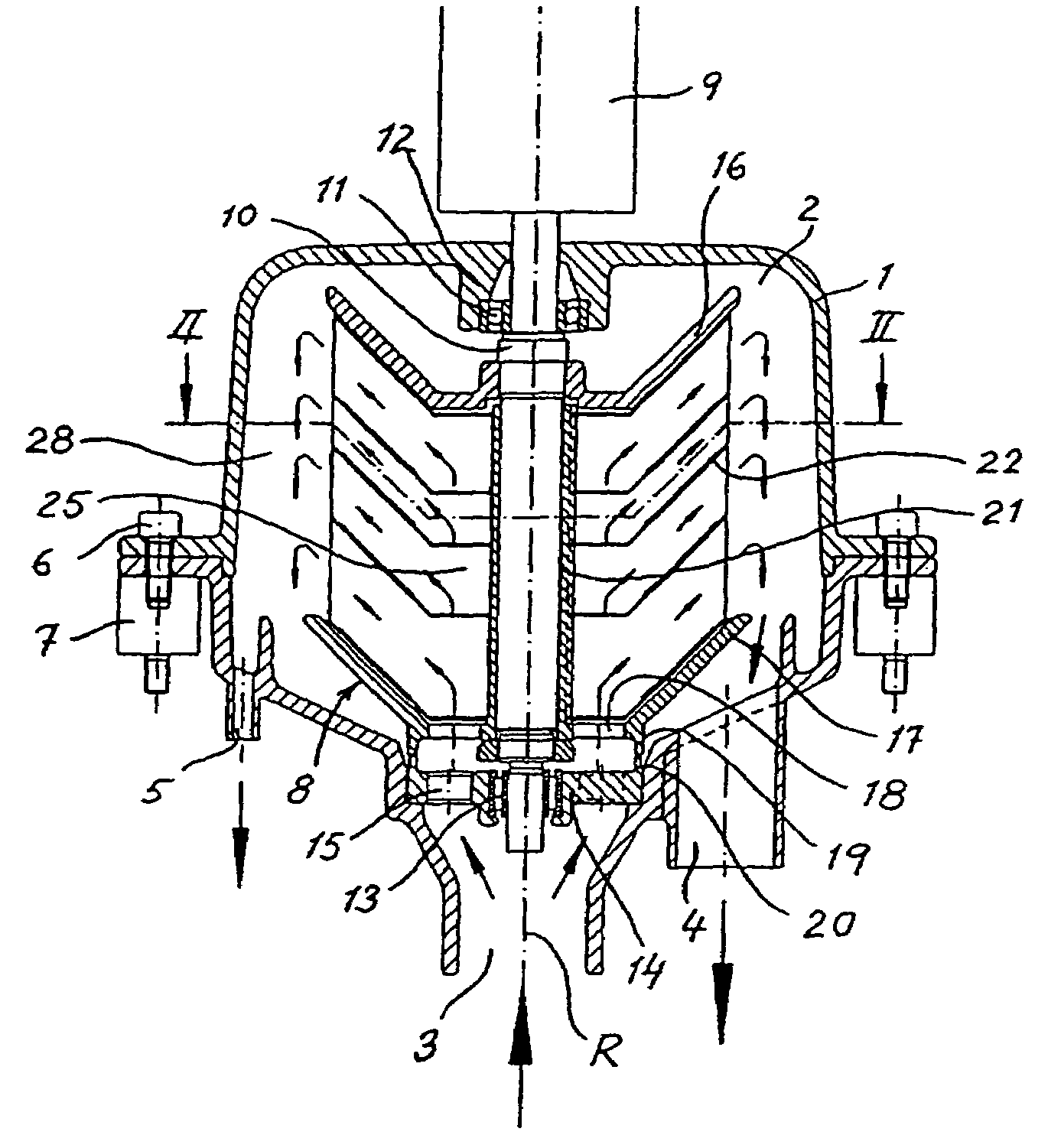
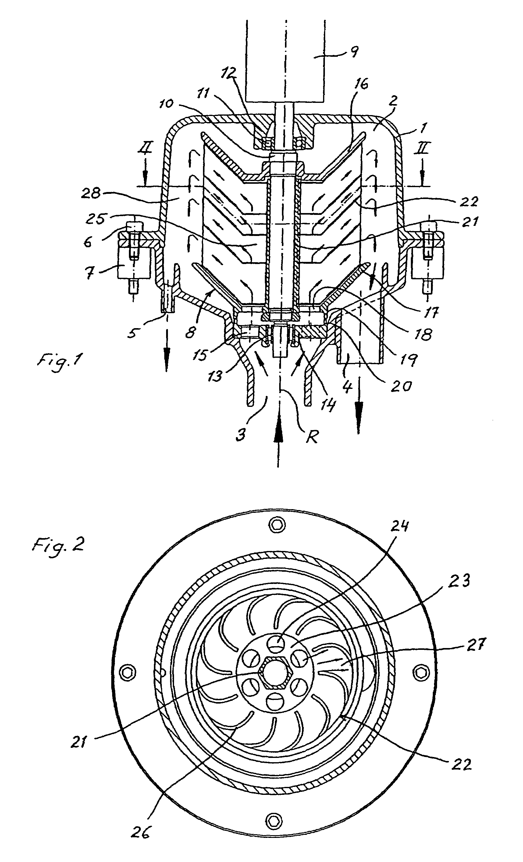
[0033]The centrifugal separator includes a housing 1 delimiting a chamber 2. The housing forms a gas inlet 3 to the chamber 2 for gas to be cleaned and a gas outlet 4 from the chamber 2 for clean gas. The housing further forms a particle outlet 5 from the chamber 2 for particles having been separated from the gas.

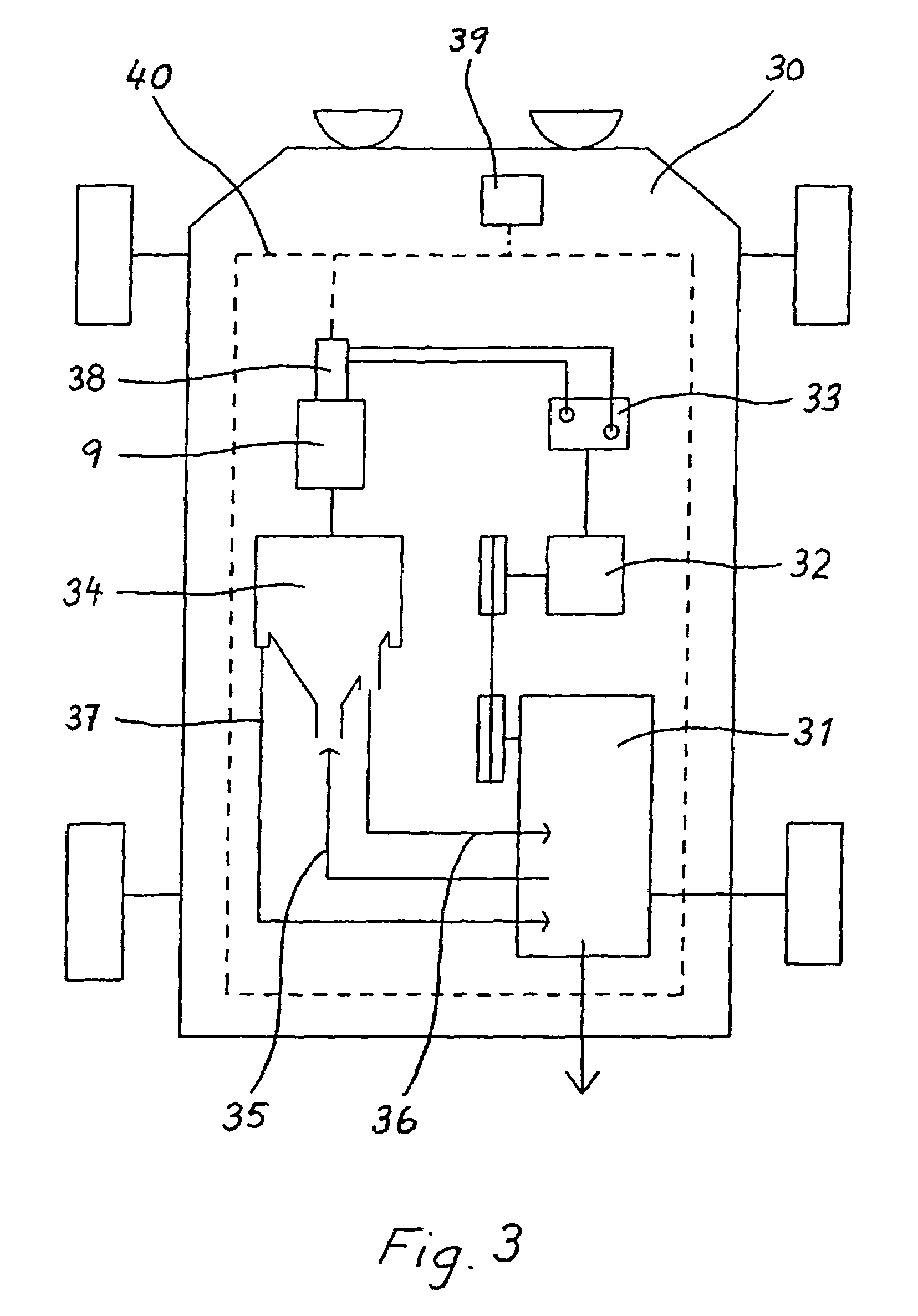
[0034]The housing 1 includes two parts which are kept together by means of a number of screws 6. These screws 6 are also adapted to fix the housing to suspension members 7 of some elastic material, through which the housing may be supported on said vehicle (not shown).

[0035]Within the chamber 2 a rotor 8 is arranged rotatable around a vertical rotational axis R. An electrical motor 9 is arranged for rotation of the rotor 8. The rotor 8 includes a vertically extending central spindle 10, which at its upper end is journalled in the housing 1 through a bearing 11 and a bearing carrier 12 and at its lower end is journalled in the housing I through a bearing 13 and a bearing car...


PUM

PropertyMeasurementUnit
pressureaaaaaaaaaa
voltageaaaaaaaaaa
voltageaaaaaaaaaa

Abstract

Upon cleaning of crankcase gas generated during operation of an internal combustion engine in its crankcase, a centrifugal separator is used, which includes a rotor arranged for rotation by means of a driving motor and arranged by its rotation suck crankcase gas from the crankcase through a conduit to the centrifugal separator. During operation of the combustion engine a parameter, e.g. a measurement of the load on the combustion engine is sensed, the magnitude of said parameter being related to the amount of crankcase gas generated per unit of time in the crankcase. Depending upon a sensed change of the sensed parameter the rotational speed of the rotor of the centrifugal separator is changed in a way such that the gas pressure in the crankcase is maintained at a predetermined value, or within a predetermined pressure interval, during the operation of the combustion engine.

Description

CROSS-REFERENCE TO RELATED APPLICATIONS[0001]This application is entitled to the benefit of and incorporates by reference essential subject matter disclosed in International Application No. PCT / SE2003 / 001031 filed on Jun. 17, 2003 and Swedish Patent Application No. 0201933.9 filed on Jun. 20, 2002.FIELD OF THE INVENTION[0002]The present invention relates to a method and a device for cleaning of crankcase gas that is generated during operation of an internal combustion engine in its crankcase. Internal combustion engines are used for different purposes, e.g. for propelling of transportation means on land, on sea or in the air, for performing mechanical work or in stationary or mobile plants for production of electric current.BACKGROUND OF THE INVENTION[0003]Cleaning of crankcase gas requires a cleaning device, which can effectively separate very small particles, solid and / or liquid, suspended in the crankcase gas. Different types of cleaning devices have been proposed, such as tradit...

Claims


Application Information

Patent Timeline
Patent Type & Authority Patents(United States)
IPC IPC(8): F01M13/04B01D45/14B04B5/08B04B9/10F01M13/00B04B5/12F01M1/00
CPCB01D45/14B04B5/12B04B9/10F01M13/04B04B2005/125F01M2013/0005F01M2013/0422Y10S55/19F01M11/10B04B5/08
Inventor EKEROTH, MATSCARLSSON, CLAES-GORANRIDDERSTRALE, ROLFSKOOG, JANSTROM, GORANWASE, CLAES
Owner ALFA LAVAL CORP AB
Why Eureka
Try Eureka